|

Engine Top End Assembly (June 16, 2009)
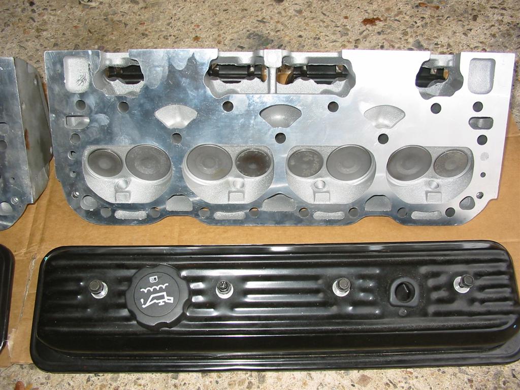
This page documents the completion of the engine build. Back in November I completed the bottom end of the engine build. Now I have completed the top end of the engine build. I am installing a set of L-98 Aluminum Heads casting number 10088113. These heads were also used on the ZZ4 engines. These are not the greatest flowing heads but should work fine on my mild 327 engine. These heads have 58cc combustion chambers, 1.94 intake and 1.50 exhaust valves and angle plugs. The aluminum heads will also remove nearly 50 lbs off of the front of the car and will give me a compression of 9.88 to 1.I also decided on using a Holley 300-36 Street Dominator Intake Manifold. This manifold is a true high rise manifold based on the original Z28 manifold. It's a dual plane manifold with an operating range of idle to 7200 RPMs.
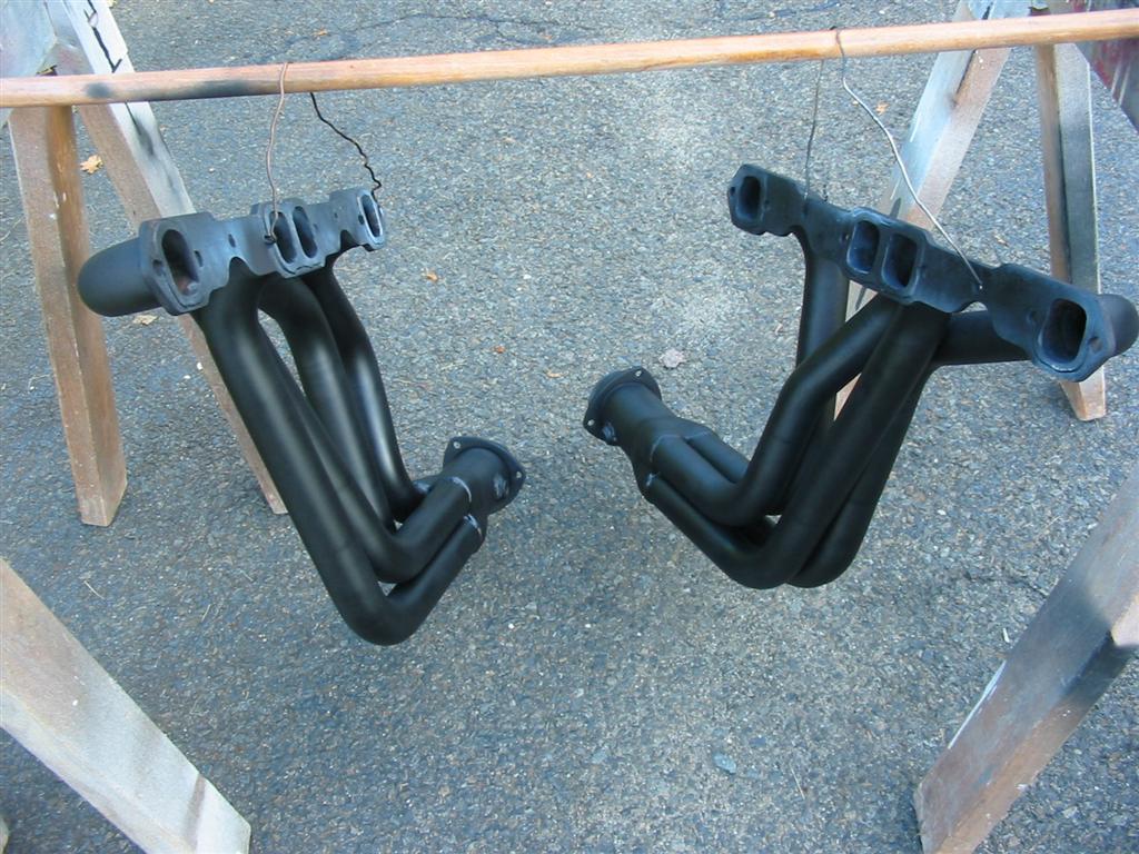
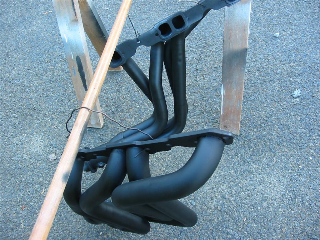
Also included on this page is the preparation of my headers. I started with a set of new Hedman Husler Hedders with 1 3/4 inch Primary Tubes and 3 inch collectors with a Ball and socket flange. I welded in O2 sensor bungs in case I ever want to install O2 sensors in the bottom. I also stripped the shipping paint and coated them with VHT Flameproof paint. This paint is capable of providing protection at temperatures of up to 1,500 degrees F according to the can.
According to Engine Analyzer Pro 3.0 my engine the engine's Peak Torque will be 351 Ft/Lbs at 4500 RPM and Peak Horsepower will be 357 HP at 6000 RPM.
Status photos as of 6/16/2009:
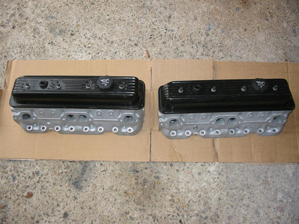
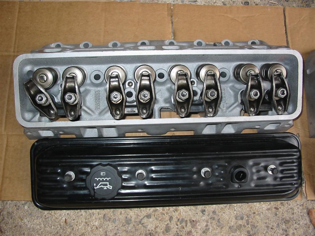
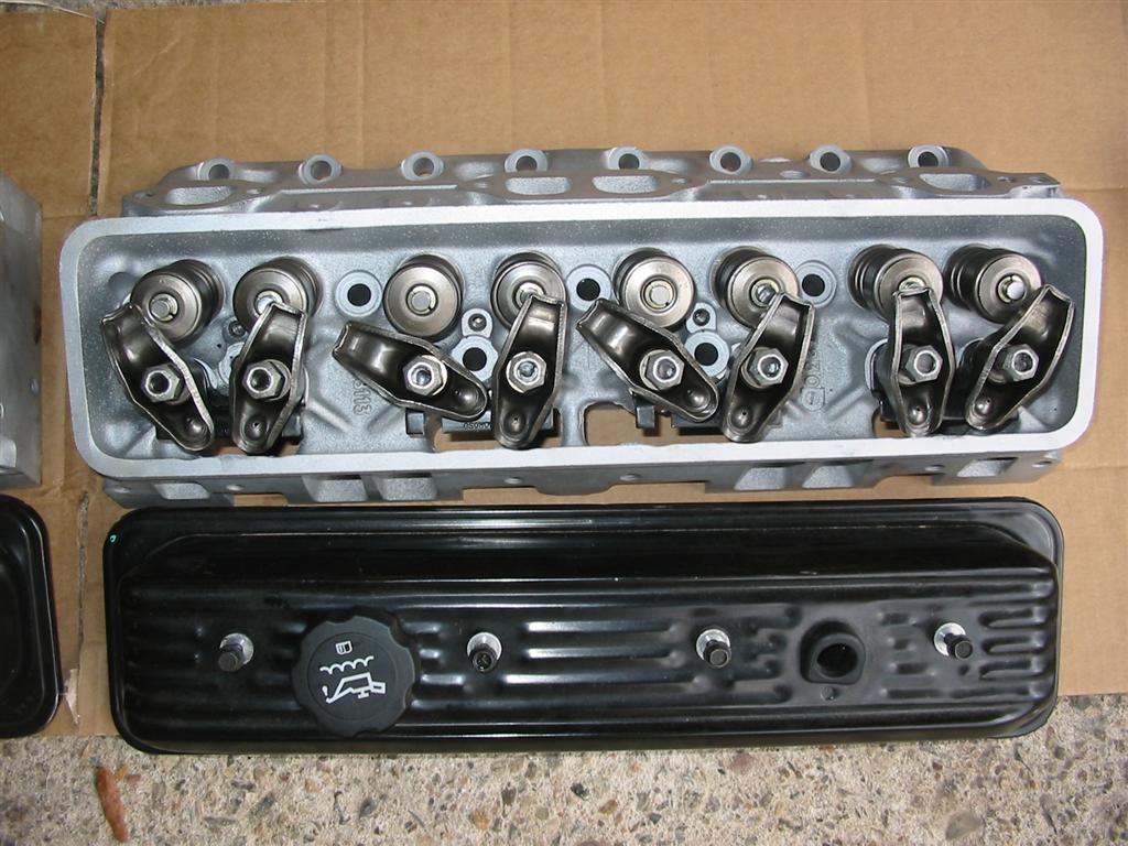
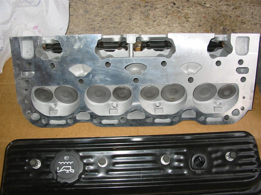
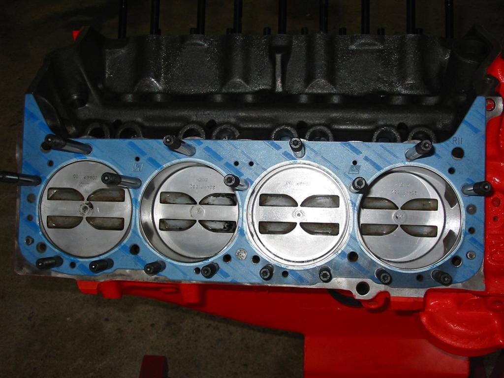
| Here are pictures of the heads before installation. I purchased the heads without rocker arms and used the rocker arms off of the original heads. | |
|
|
|
|
|
|
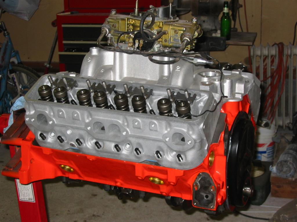
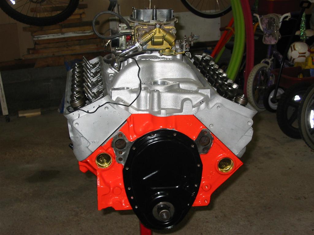
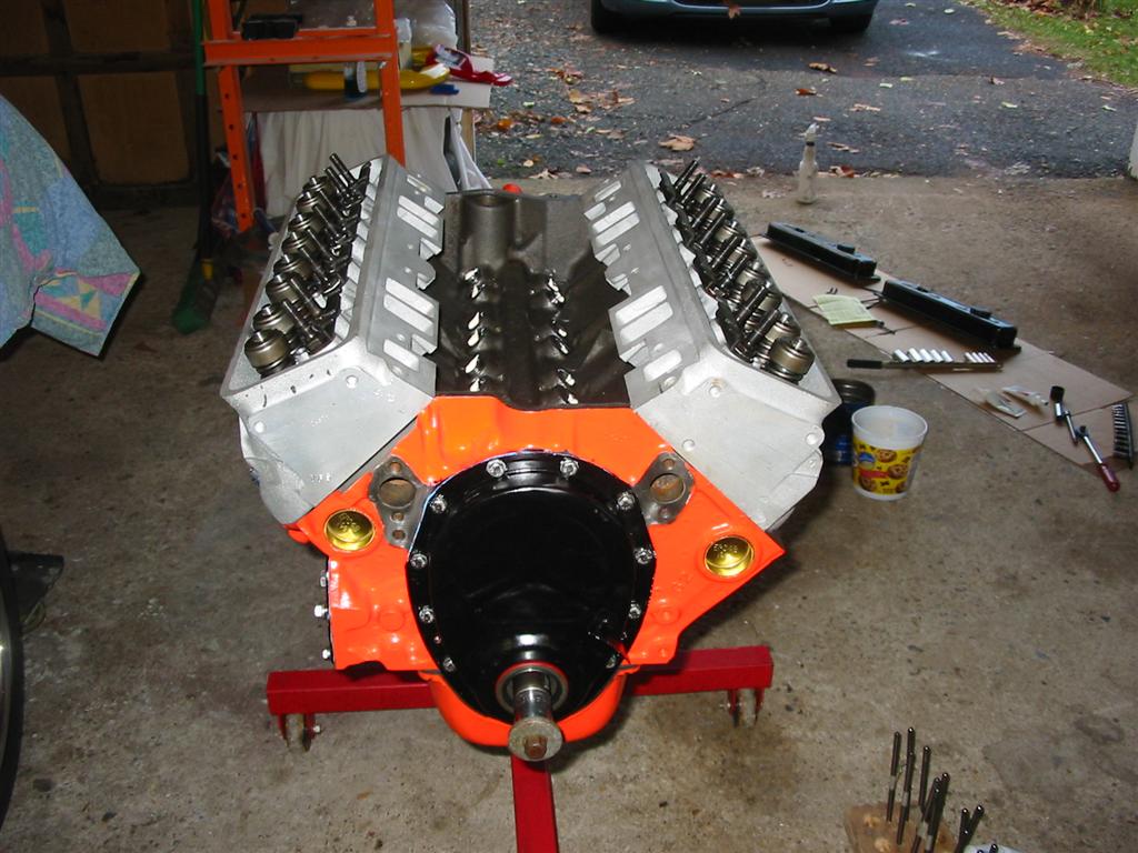
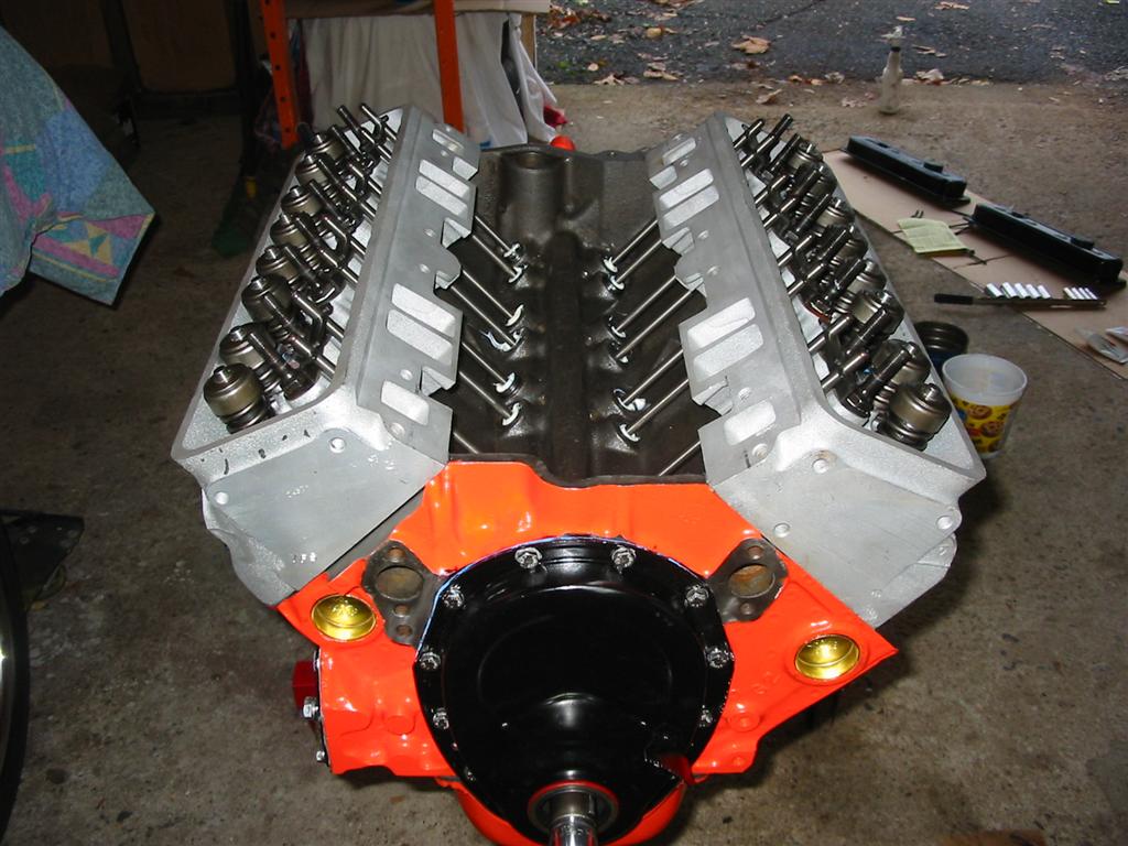
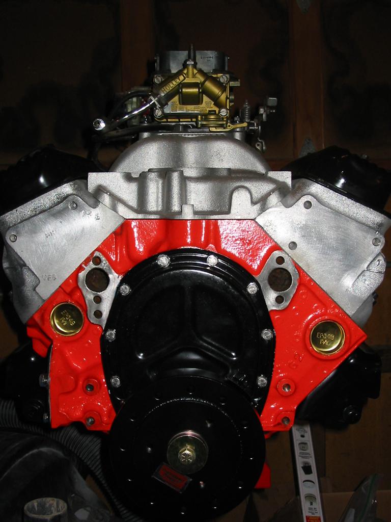
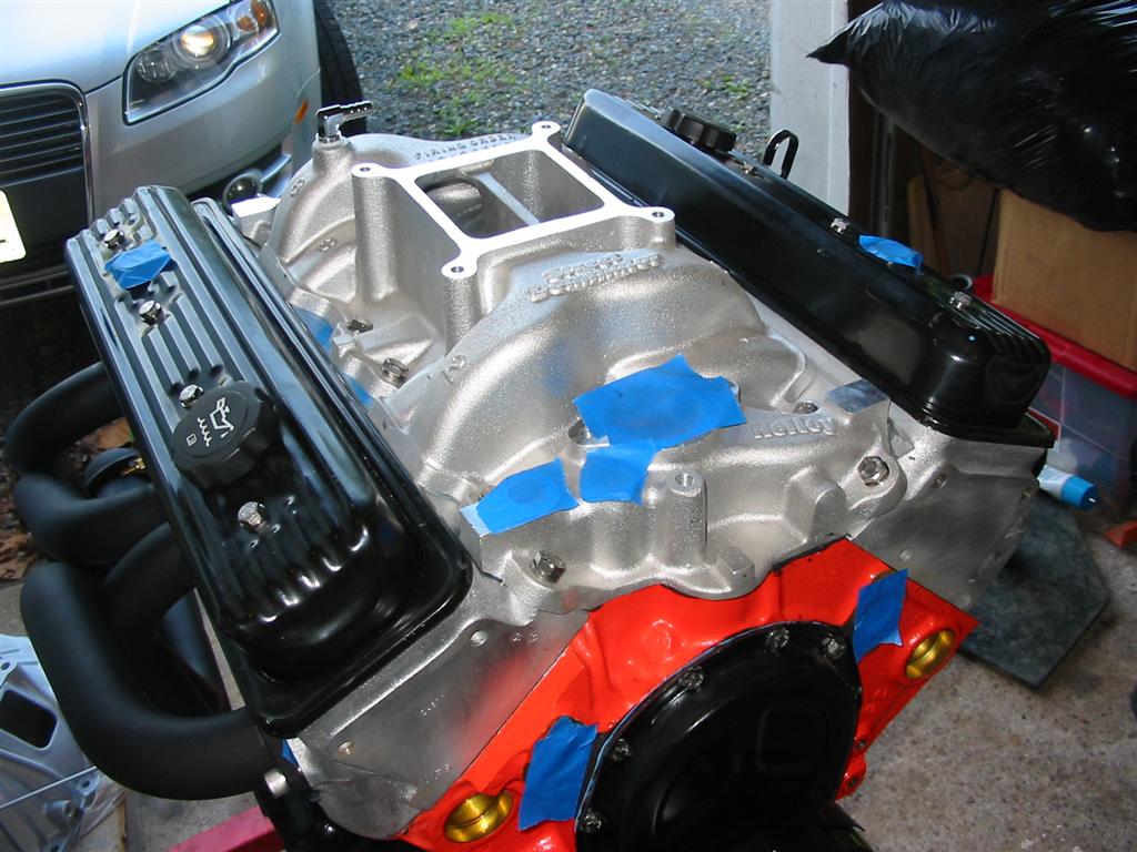
| Here is a picture of a mockup of the engine with the heads and intake. Neither are installed at this point. I was just test fitting them. | |
|
|
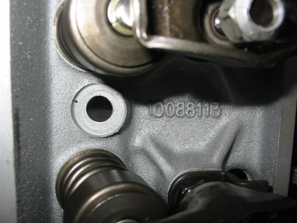
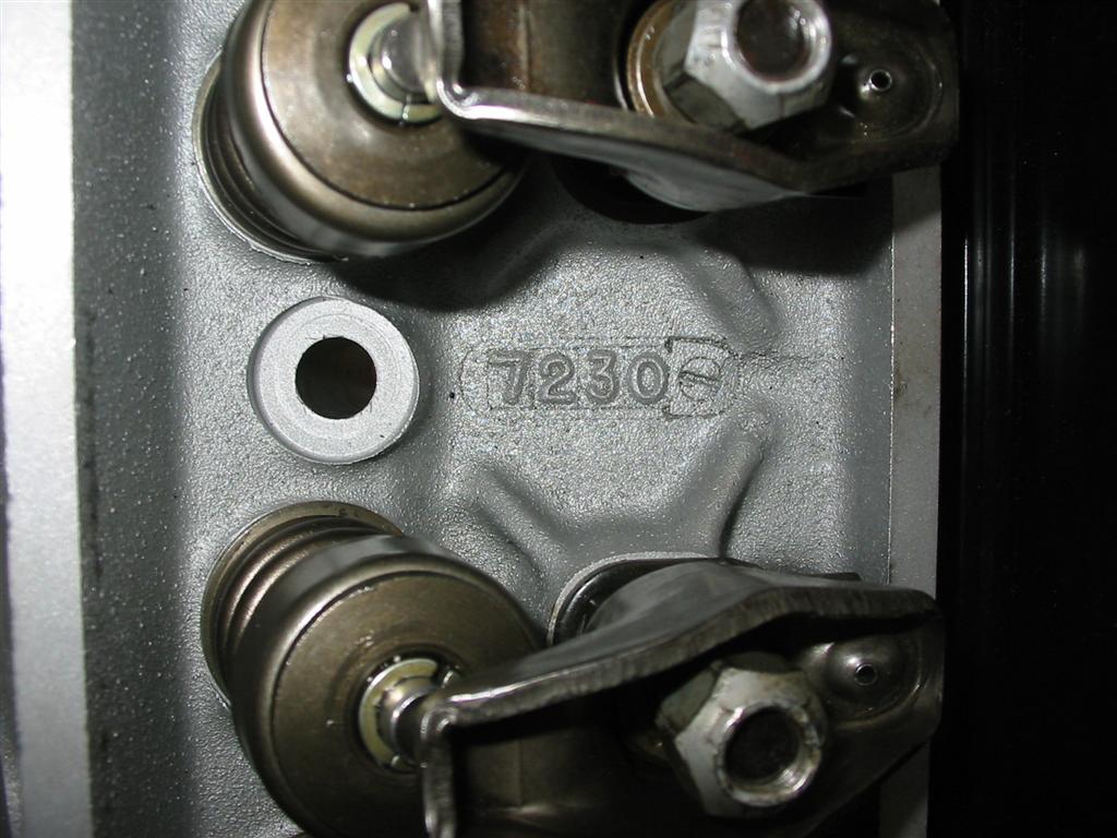
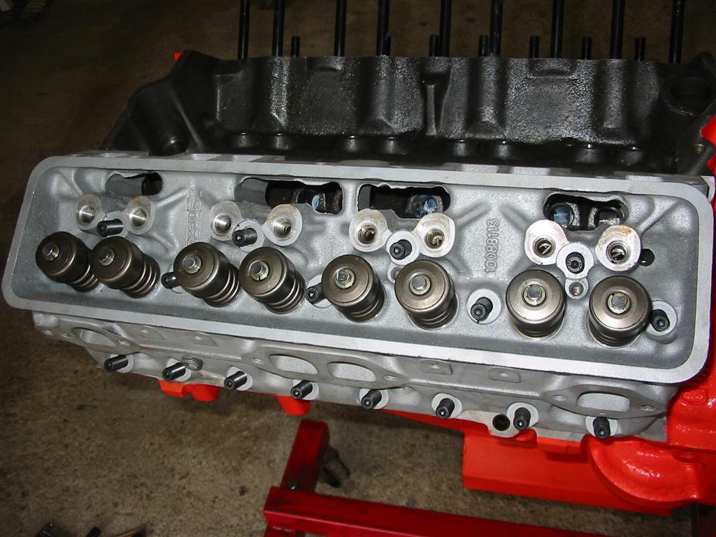
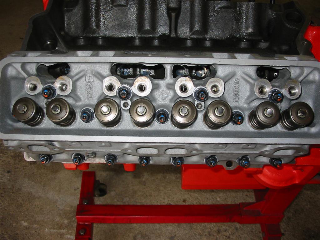
| Here are the casting numbers off of the heads. | |
|
|
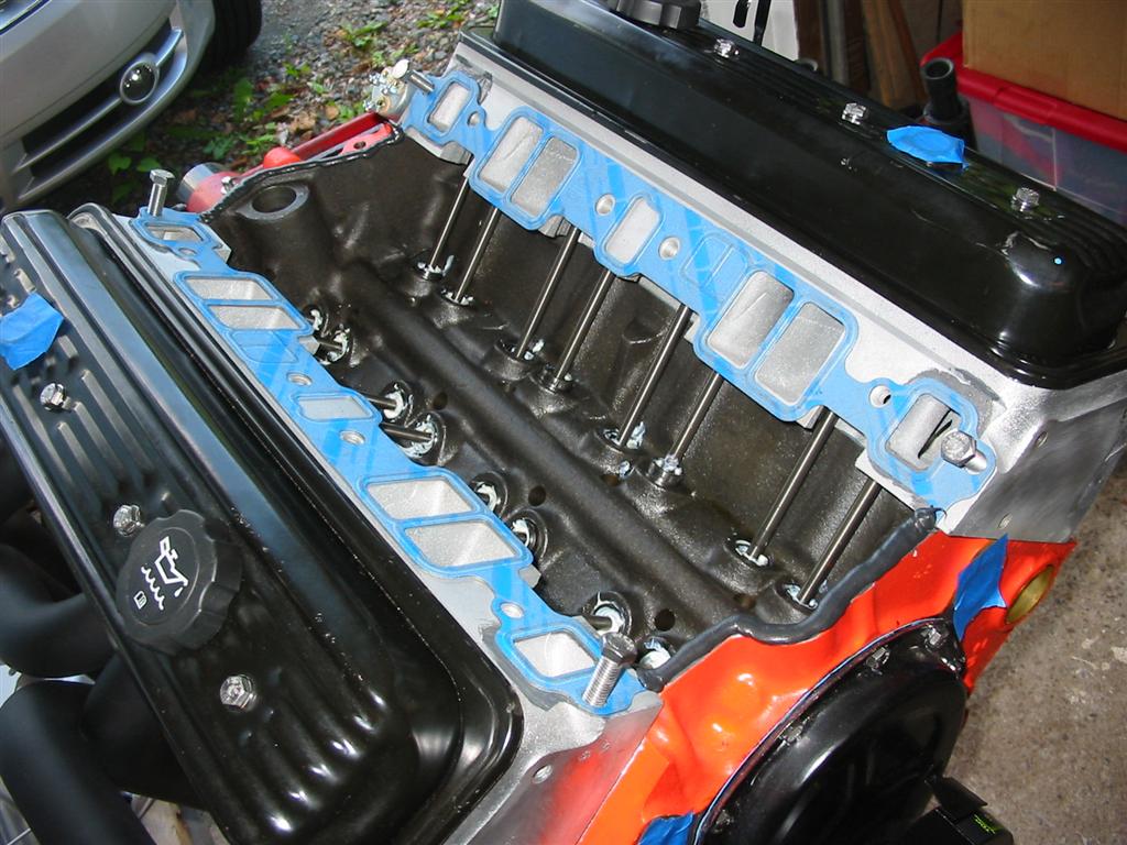
| Here is the head gasket in place on the block over the head studs. | Here is the head sitting on the block. |
|
|
| Here is the head installed and torqued down. | |
|
|
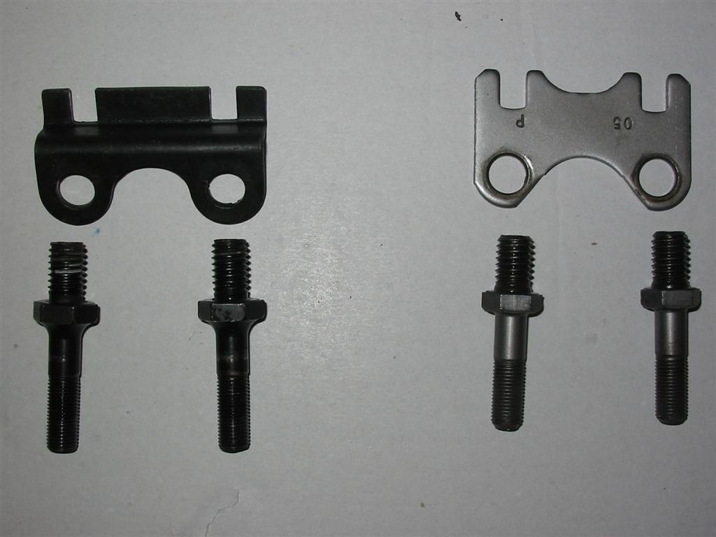
| These heads don't come with true guideplates from the factory and require self guided rocker arms with the factory guideplates. I swapped out the factory guideplates on the right with the Moroso ones on the left. I also replaced the factory screw in studs with the upgraded studs on the left. With these guideplates, I can run normal rocker arms. I also needed to modify the valve covers to fit the new guideplates. | Here are the guide plates installed. |
|
|
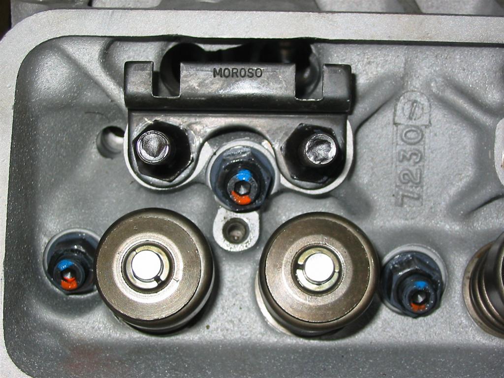
| Here is a close up of an installed guide plate. | |
|
|
| Here are the lifters installed. | |
|
|
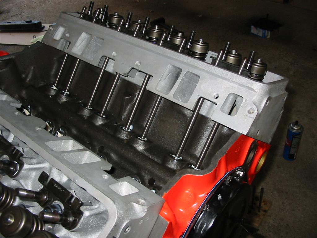
| Here are the pushrods in place. | |
|
|
|
|
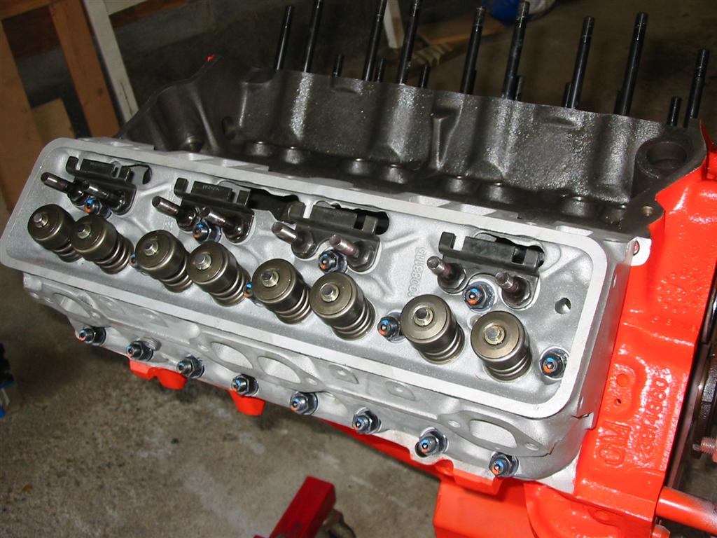
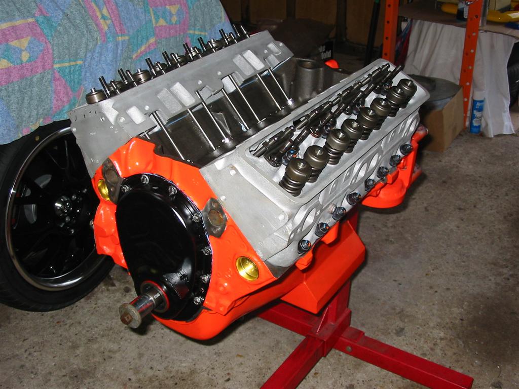
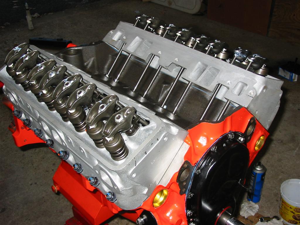
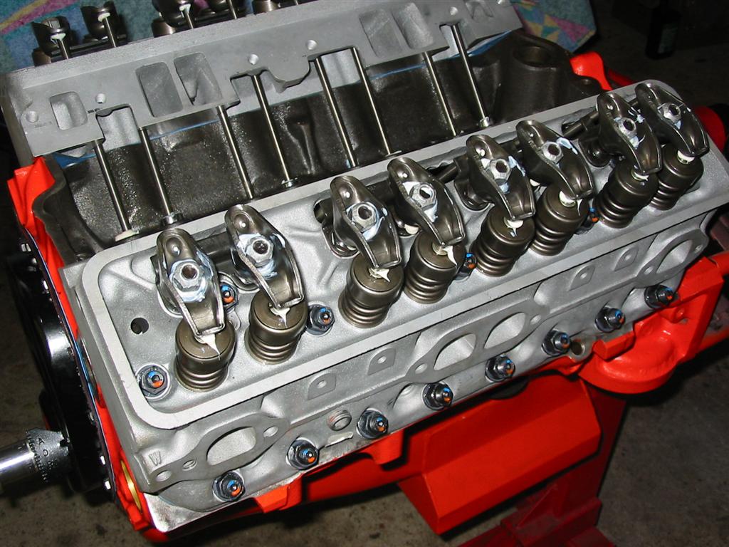
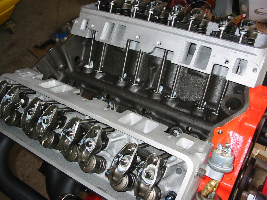
| Here are the rocker arms installed on the heads. I still need to adjust the valves at this point. | |
|
|
|
|
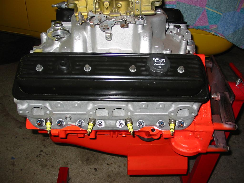
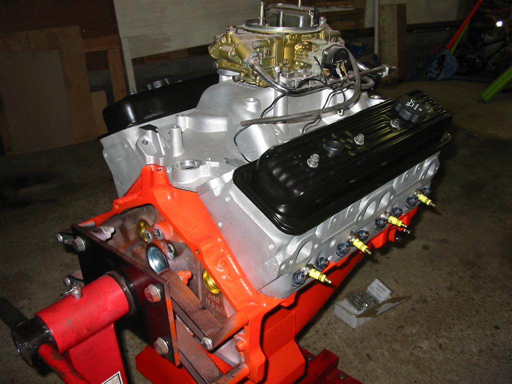
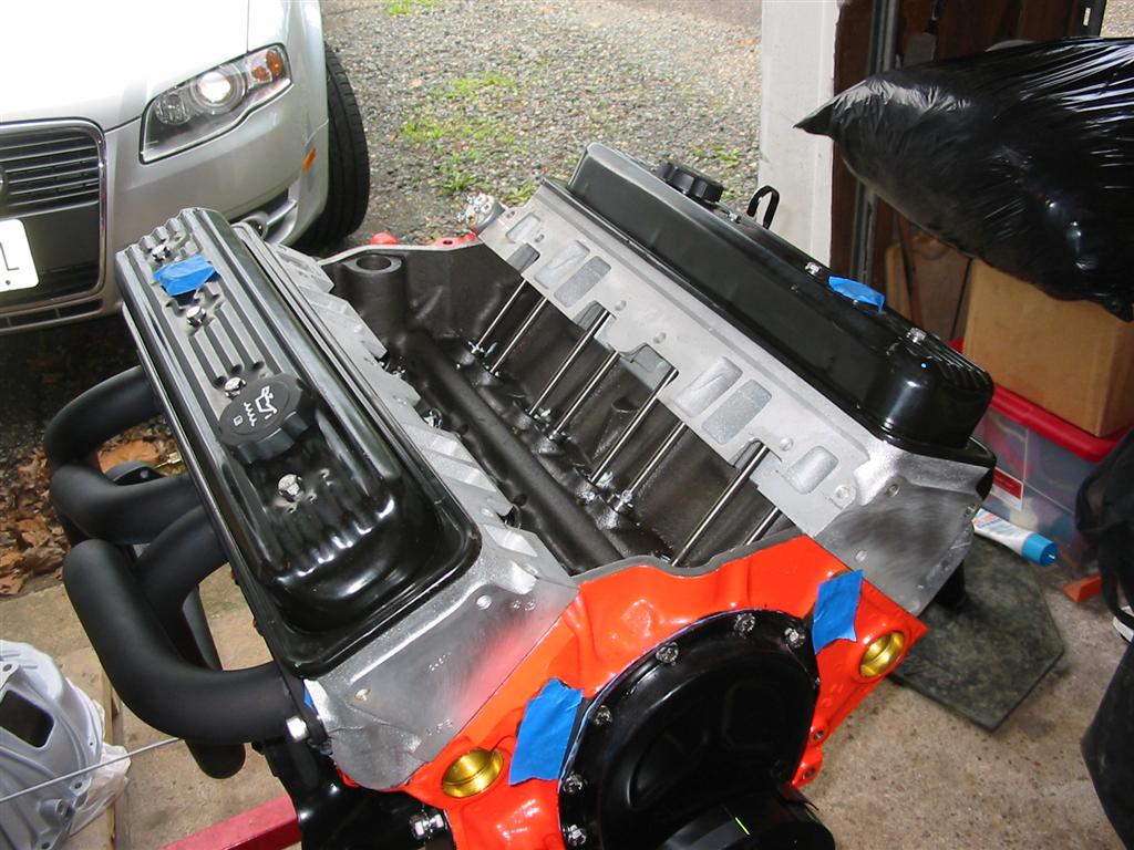
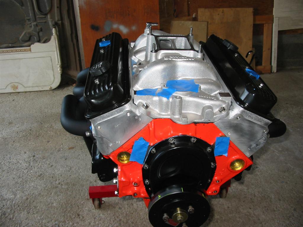
| Here are a few shots of the engine mocked up with the intake and valve covers. | |
|
|
|
|
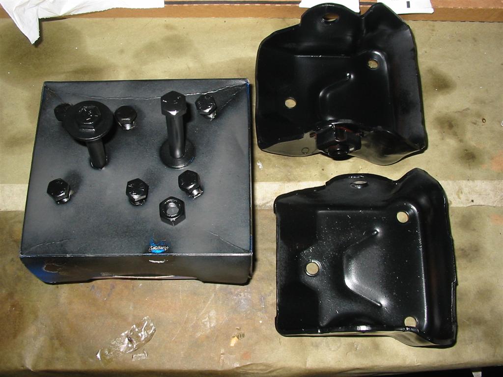
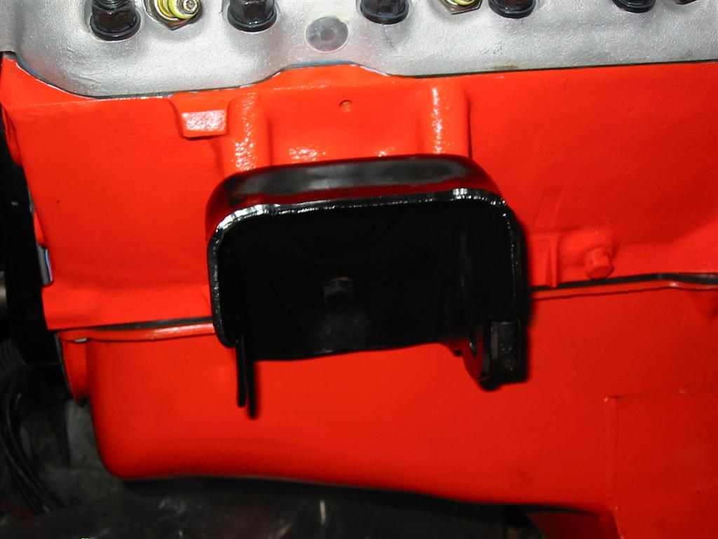
| I cleaned, painted and installed the engine mounts. | |
|
|
|
|
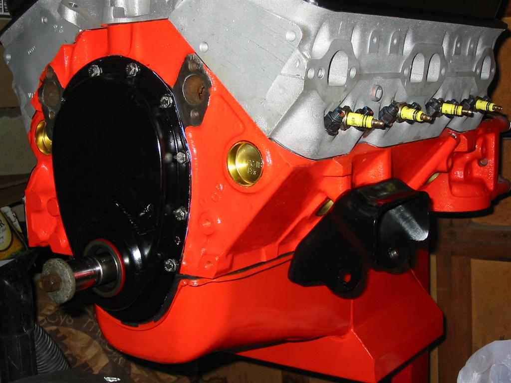
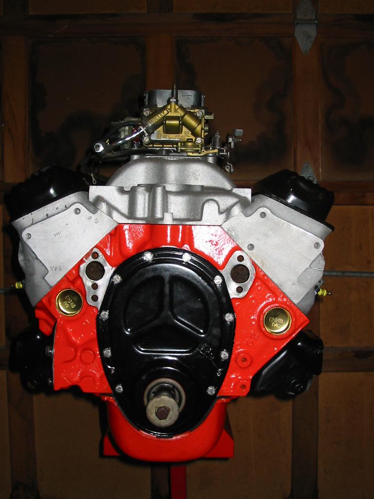
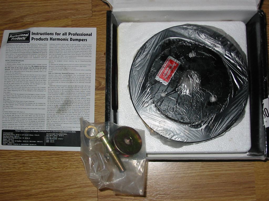
| I then purchased a Professional Products 6.75 inch balancer. | Unfortunately, the paint all peeled off when I boiled the balancer in water while installing it. Here it is installed on the engine. |
|
|
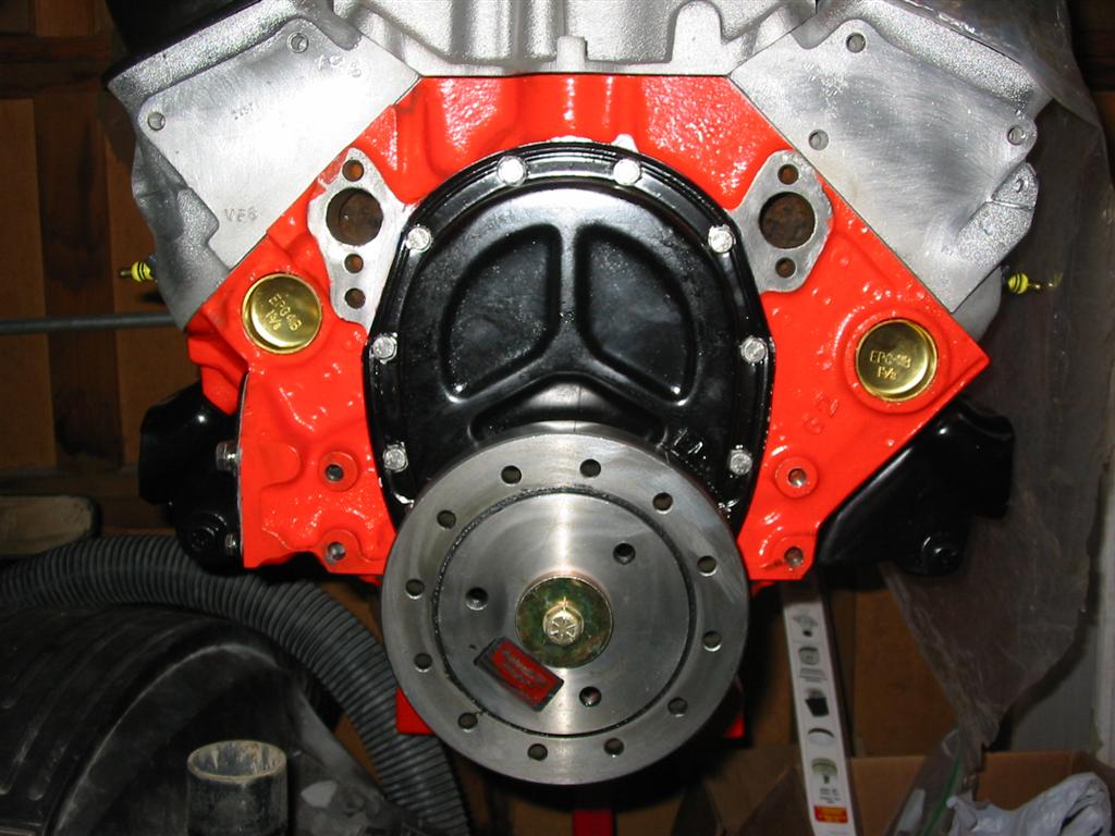
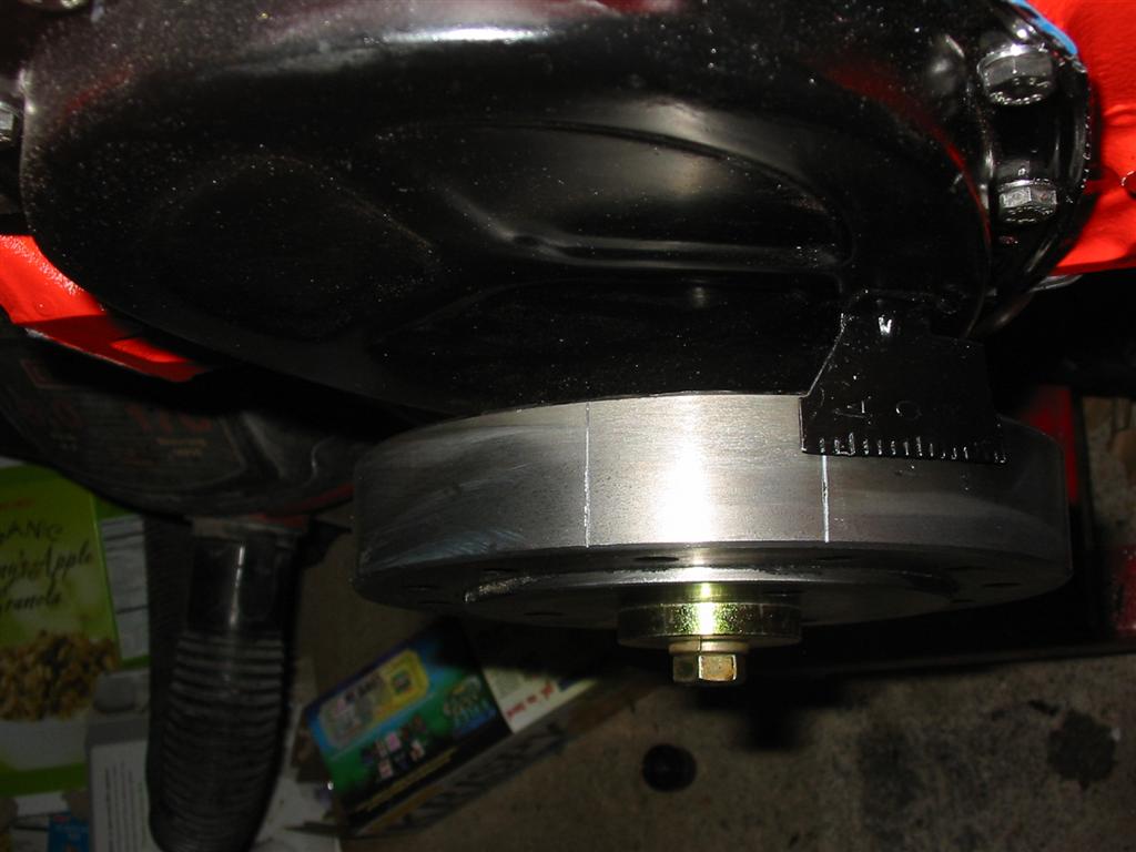
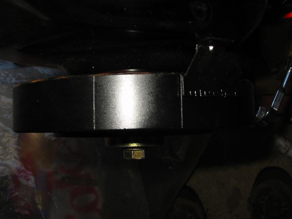
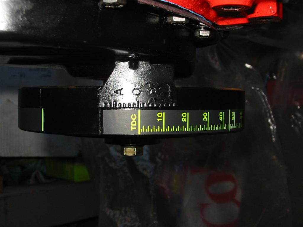
| Here is a top shot of the balancer installed. Unfortunately, the TDC marks shown do not line up. 1968 requires different marks than other years. | Here is the balancer with a coat of paint on it. |
|
|
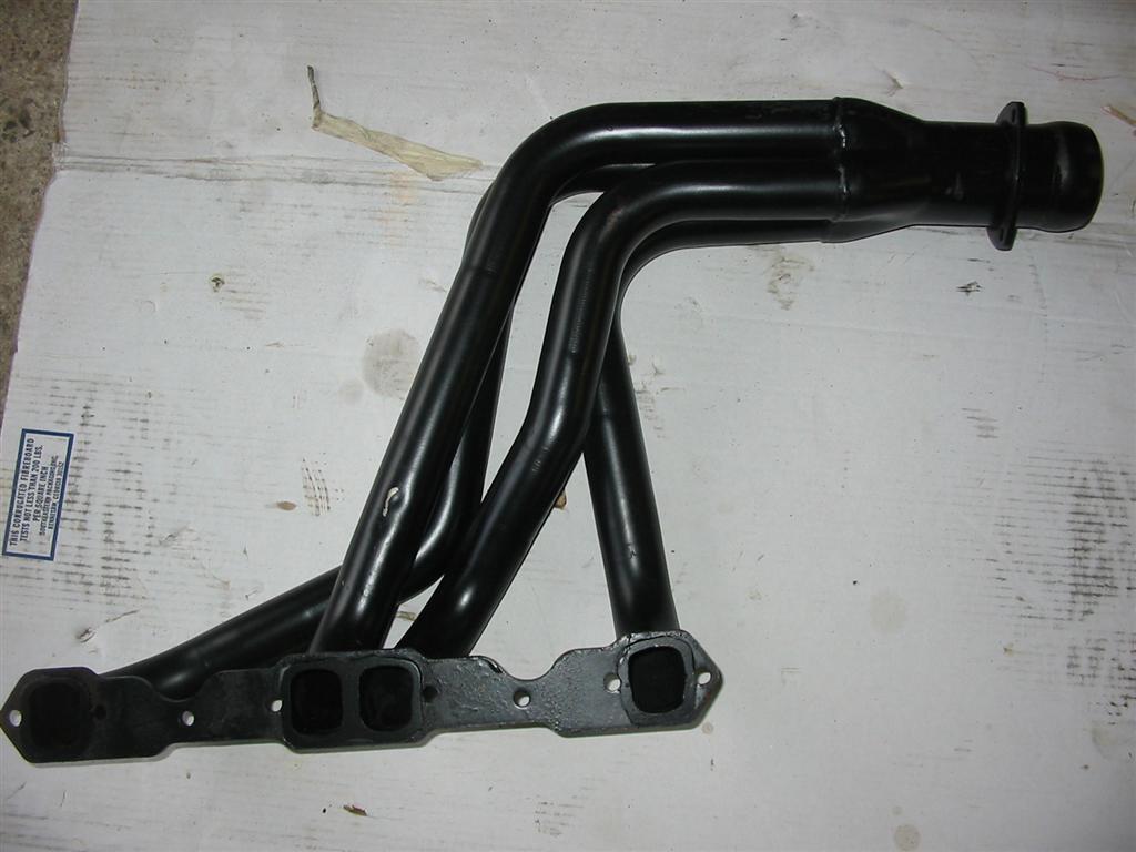
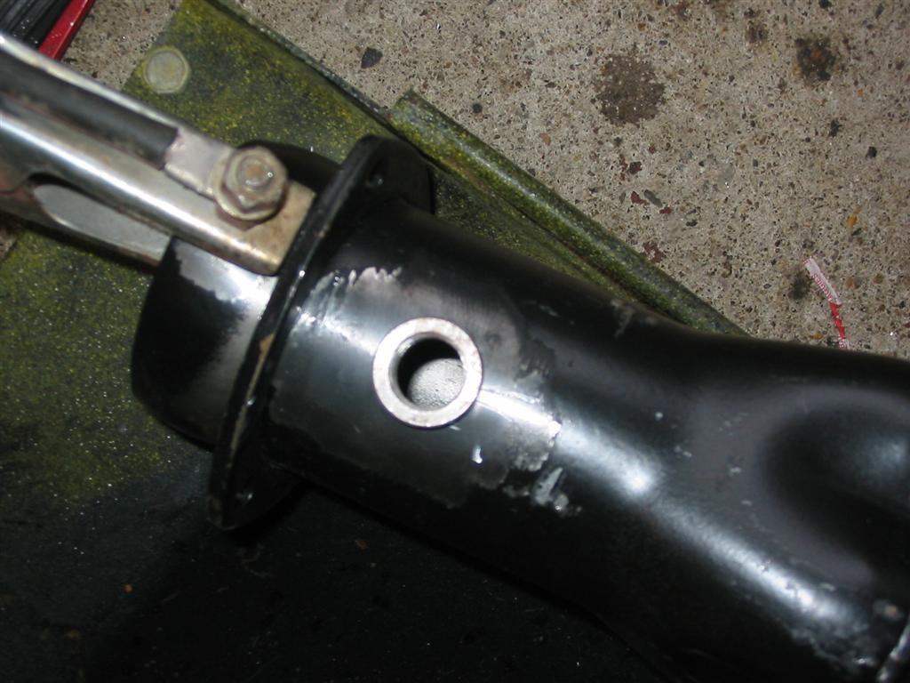
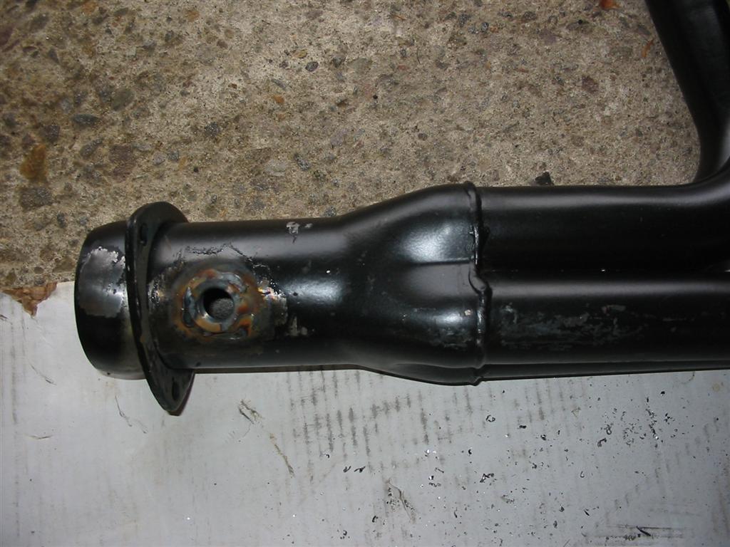
| Here is what the header looks like from the factory. This paint is just for shipping. It should be stripped and coated with a heat resistant paint or coating. | Here is the O2 sensor bung in place ready for welding. |
|
|
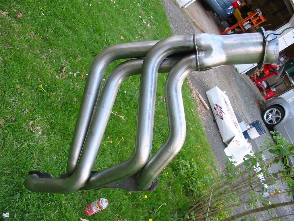
| Here is the O2 sensor bung welded into place. I then repeated this process on the other header. | Here is one of the headers with all the paint stripped. |
|
|
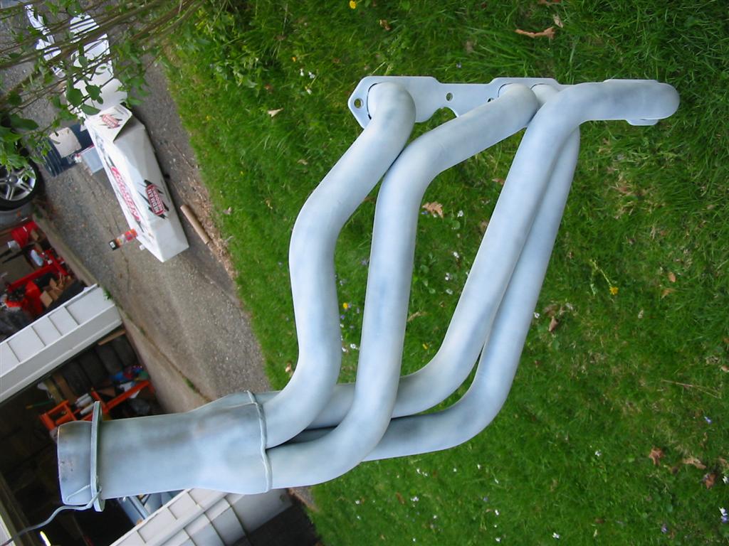
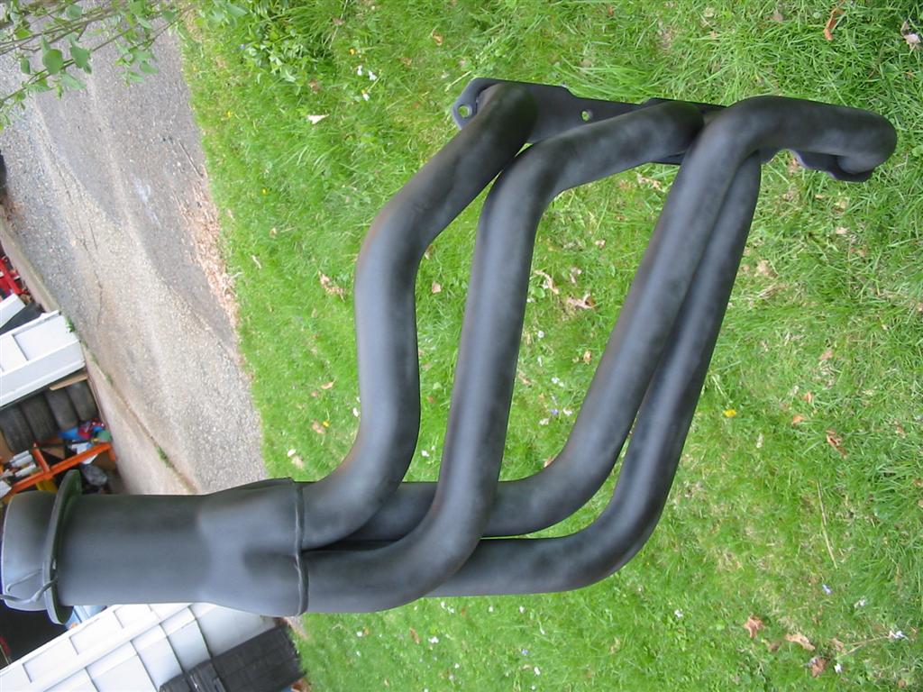
| I then primed the headers using the VHT Flameproof white | I then coated the headers in flat black using several light coats. |
|
|
|
|
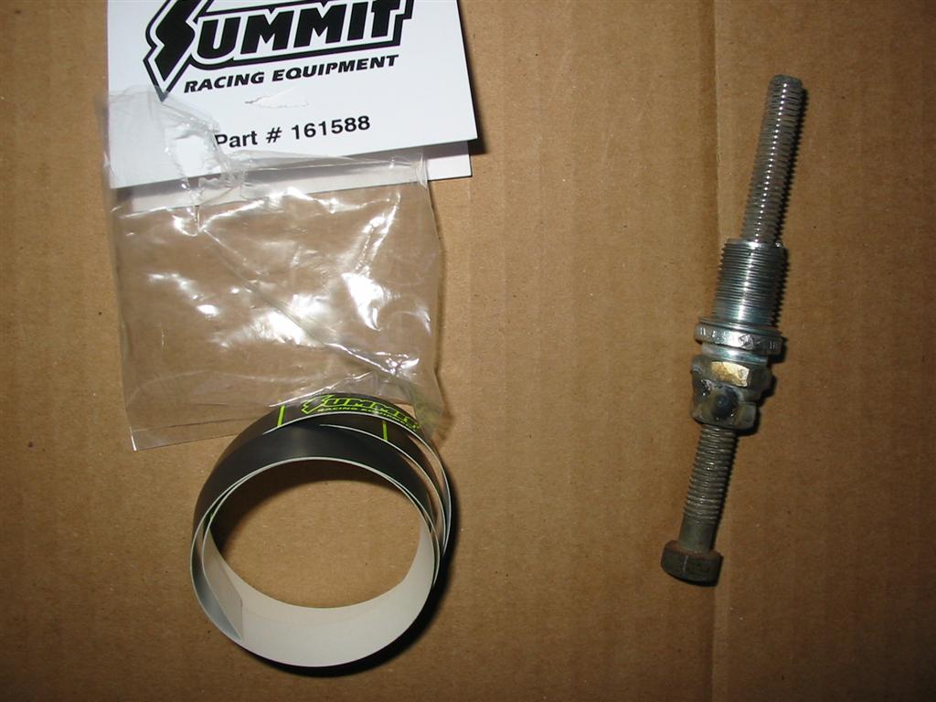
| Here is a timing tape I purchased for the balancer and a homemade piston stop. I used an old spark plug, nut and bolt to make the piston stop. I then used the piston stop to find TDC and install the tape. | Here is the balancer at TDC. |
|
|
| Here is the balancer with the tape installed. | |
|
|
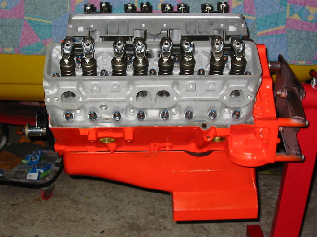
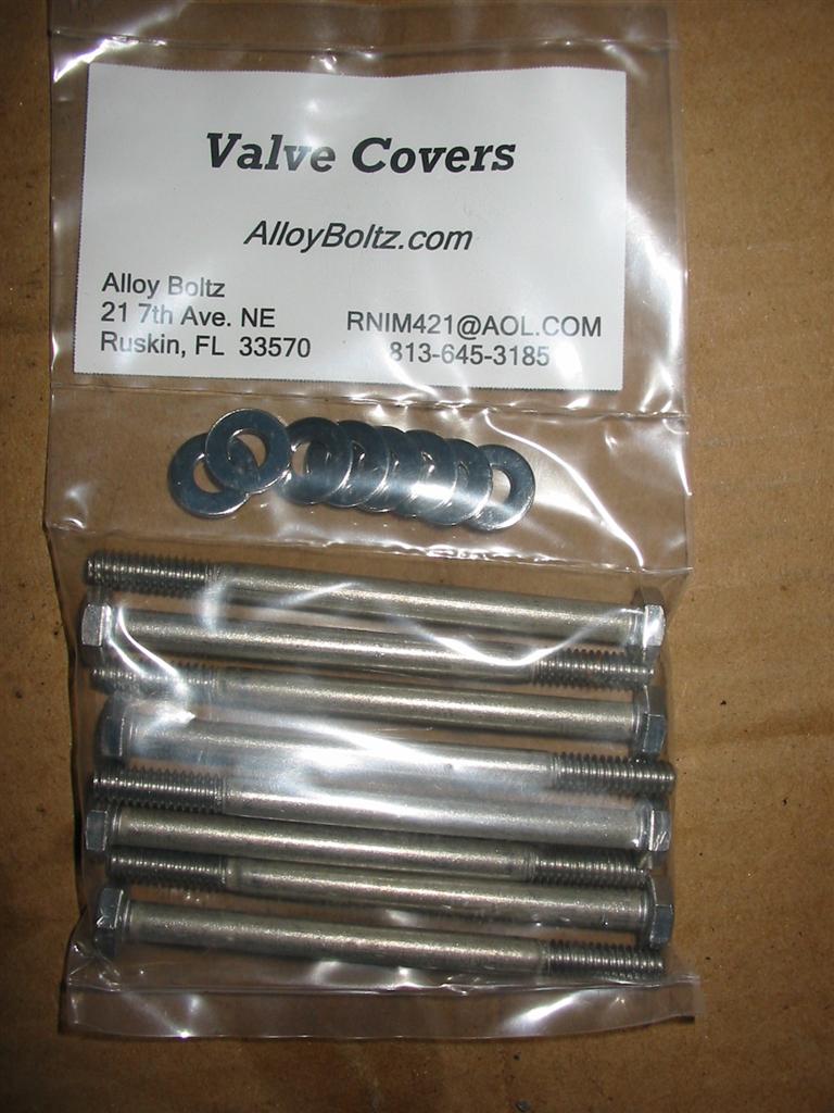
| Here is the engine with the valves adjusted and the valvetrain ready to go. | Here are my stainless steel bolts for the valve covers. |
|
|
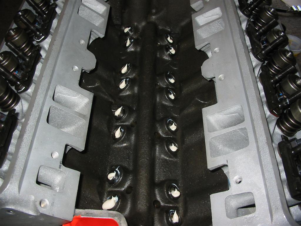
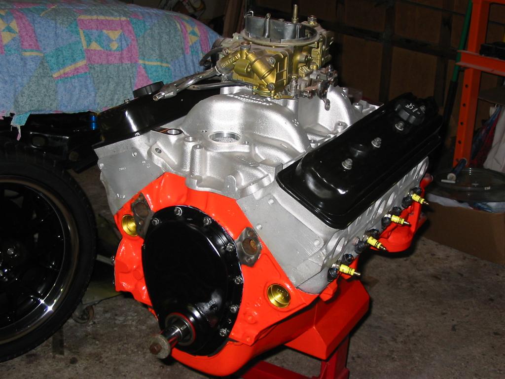
| Here are the valve covers installed. | The final step was to install the intake manifold. |
|
|
|
|
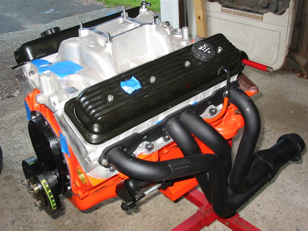
| Here is the engine assembled with the headers on for a test fit. I still need to install the distributor. I will install the distributor once the engine is in the car and the oil system has been primed. | |
|
|