|

Engine Teardown and Shortblock Buildup (November 13, 2008)
This page documents the teardown and buildup my engine. This engine is originally out of a 1968 Impala. Back in 1989 I had the engine rebuilt by Sigafoos Machine shop in Easton, PA. They bored the block .030, machined the crank .010 under, reconditioned the rods and hung .030 forged flat top pistons on the rods. They then balanced the whole assembly. This engine was used in my car for about 13 months and I put about 12,000 miles on the assembly before I put the car in storage.Originally, I decided that I was just going to replace the heads and inspect the bottom end. I needed to replace the heads because they were low performance heads without hardened exhaust seats. After inspecting the bottom end, I noticed a small vertical groove on one of the cylinder walls. I then decided to tear the bottom end apart and replace the bearings and rings. I am glad that I did, because the groove in the cylinder wall was due to a broken oil ring. Overall, the engine was in great shape. I measured all the bores and clearances and there was little to no wear on the engine.
I then honed the bores and put the bottom end together with new rings and bearings. I also added a Milodon high pressure and high volume oil pump as well as a 7 quart summit oil pan. I am also using ARP head studs and AllowBoltz.com stainless steel engine bolt kit.
Status photos as of 11/13/2008:
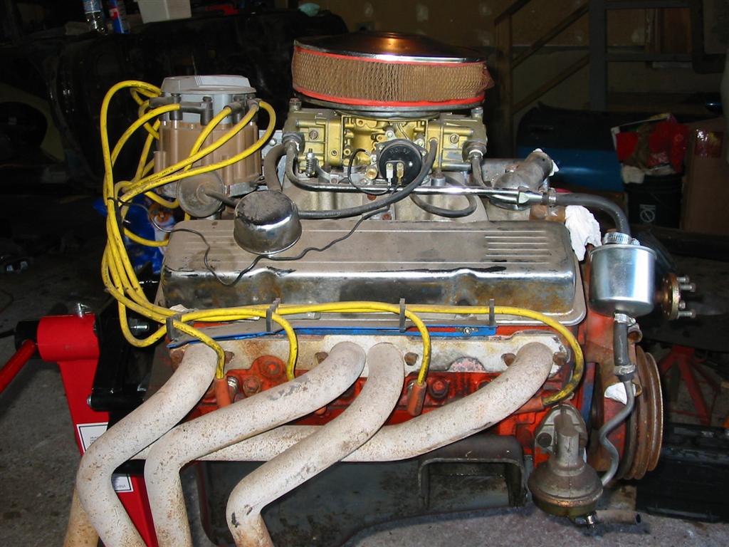
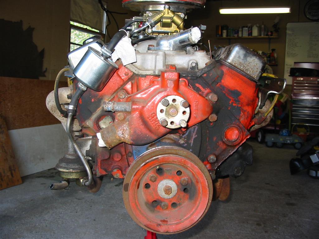
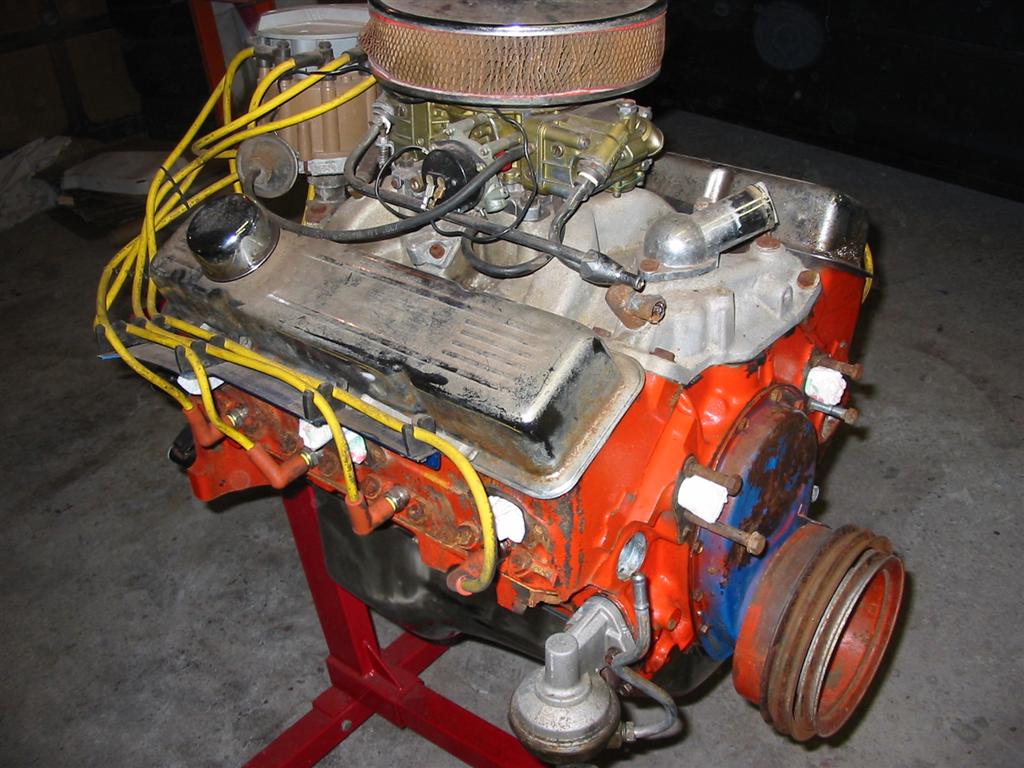
| Here is how the engine looked when I pulled it from the car. Originally, I built this engine with an Edlebrock Performer intake manifold. This manifold will be replaced with a Holly 300-36 high rise intake. | |
|
|
|
|
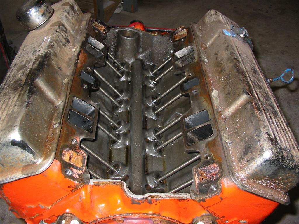
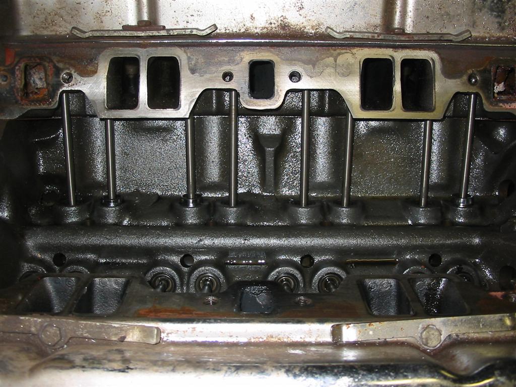
| Here are a couple of shots of the lifter valley. I was very happy with how clean and sludge free the lifter valley was. | |
|
|
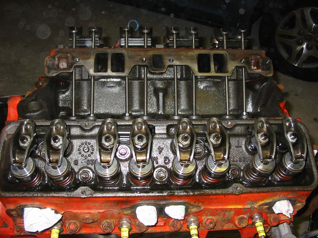
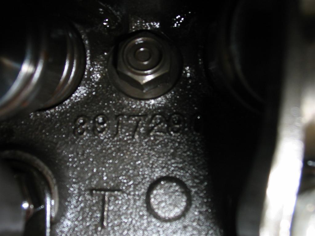
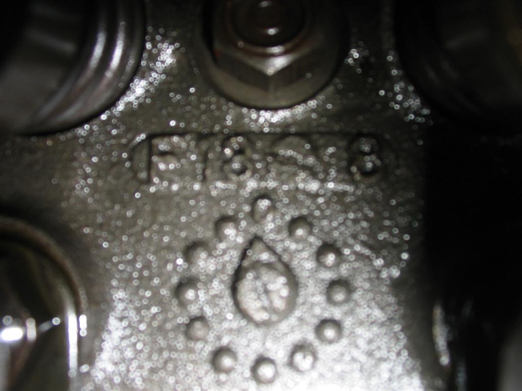
| I removed the valve cover and was also pleased with how clean the heads were. The heads were rebuilt back in 1989. I had screw in studs and guide plates added to the factory 3917290 castings. These heads are not very good from a performance standpoint. They have 68cc chambers with 1.72 intake and 1.5 exhaust valves. The port size is 142cc on the intake side with 59cc exhaust ports. These heads will not be reused in the rebuild. | |
|
|
|
|
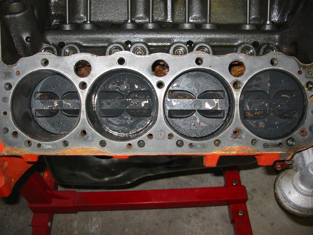
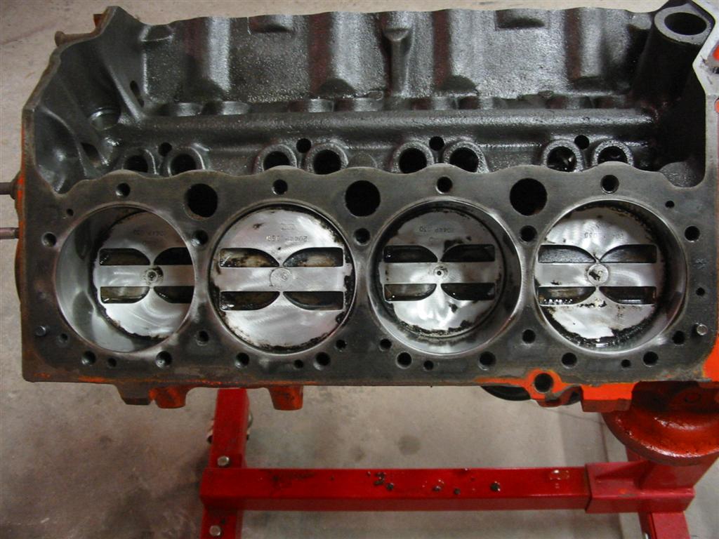
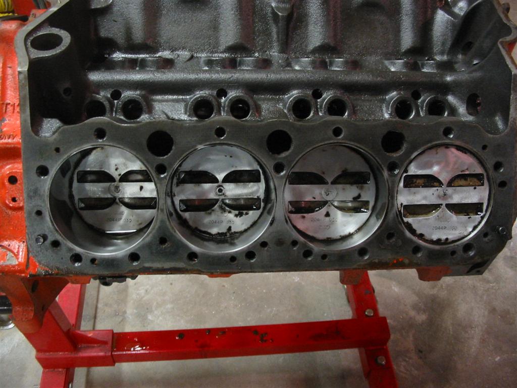
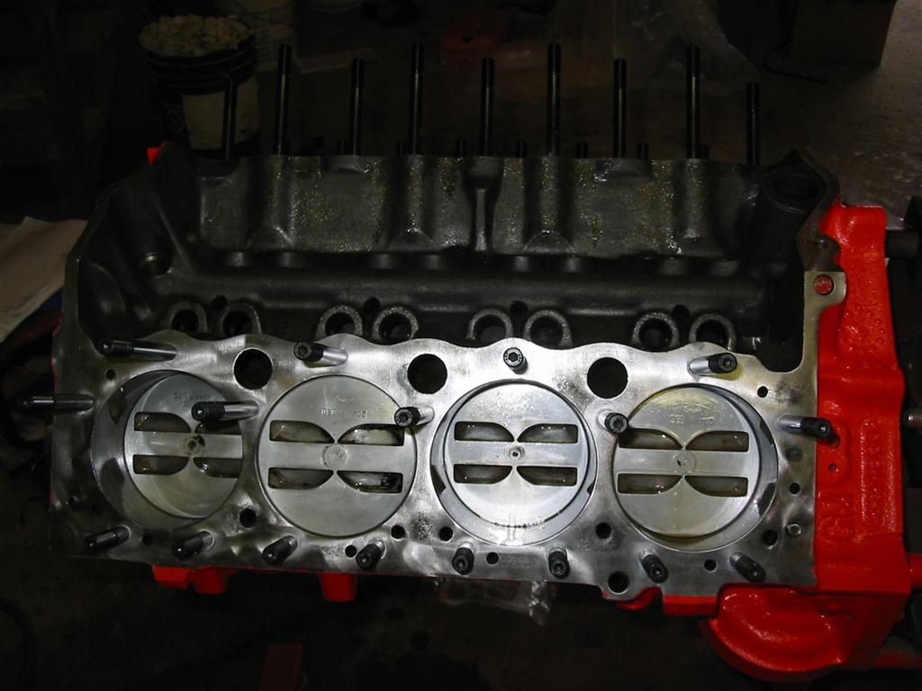
| Here a couple of shots of the pistons in the bores. The first photo is how they looked when I removed the heads. I then cleaned the pistons with a rolec disc. It was at this stage where I discovered the scratch in the cylinder bore and decided to tear down the short block and re-ring the the engine. | |
|
|
|
|
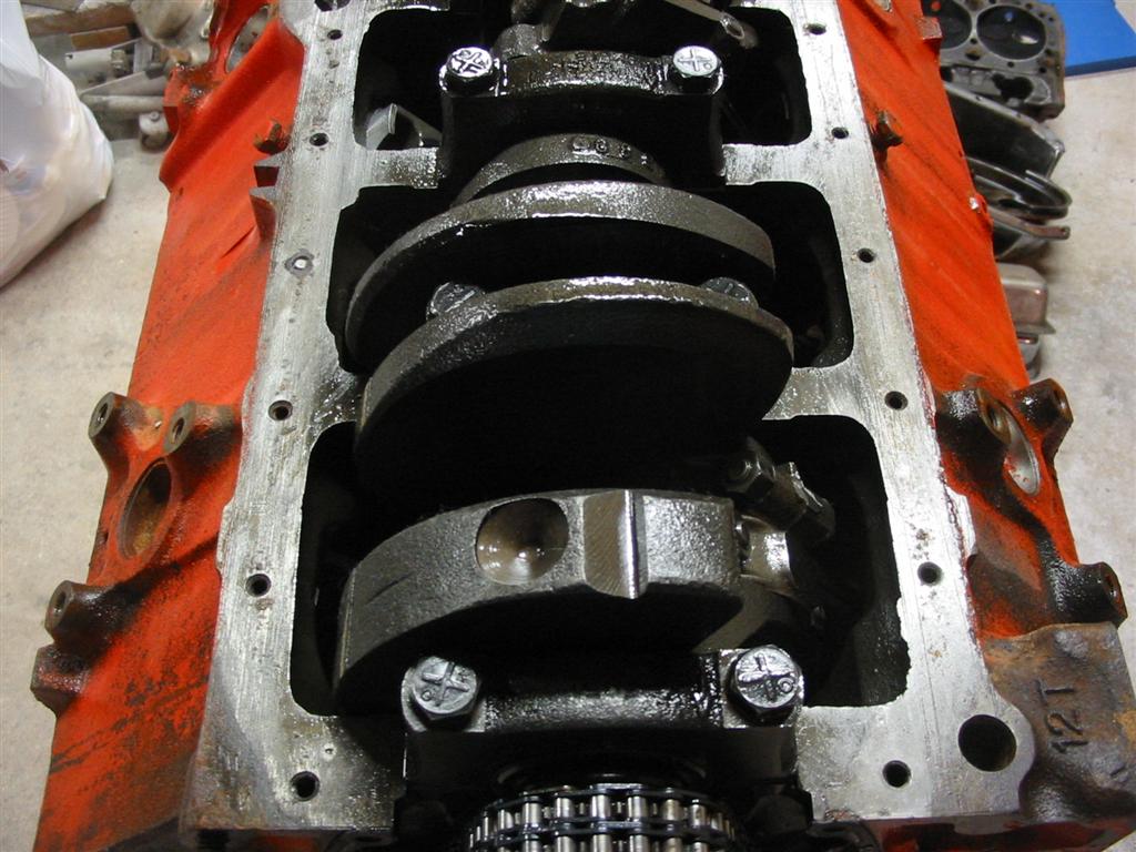
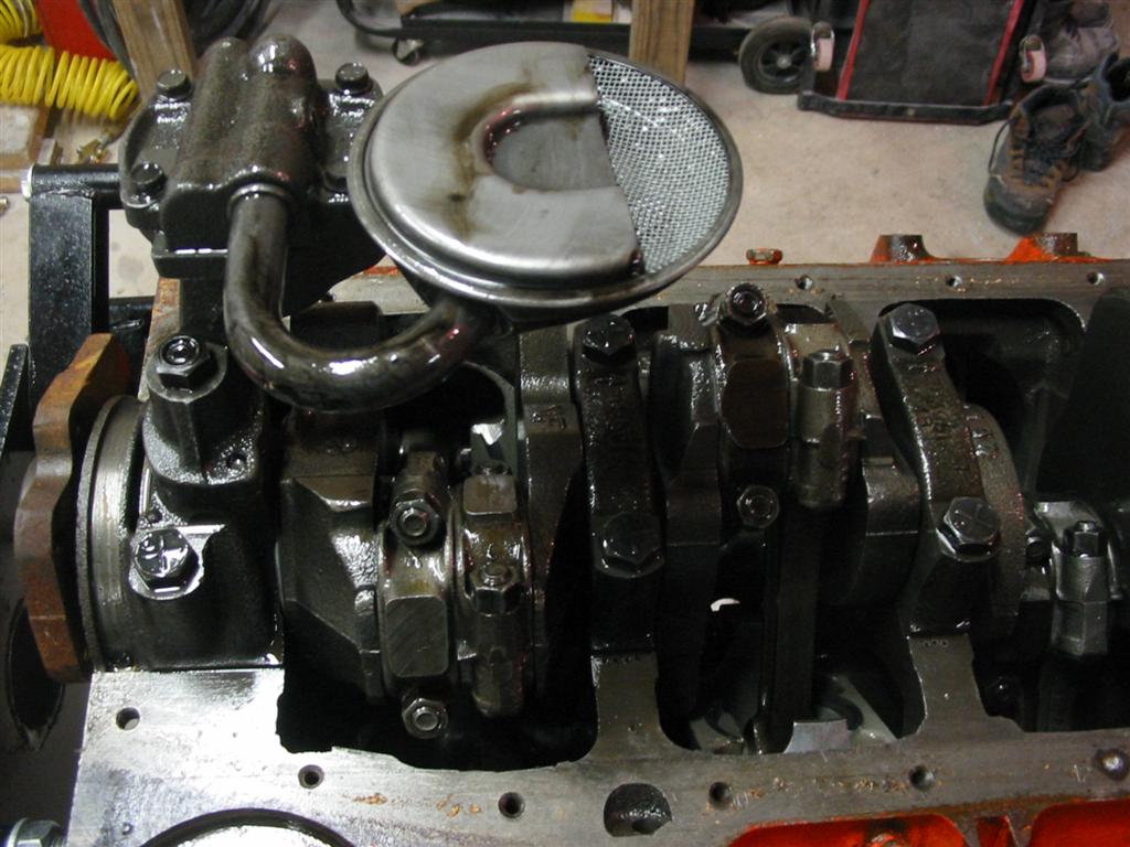
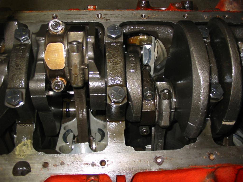
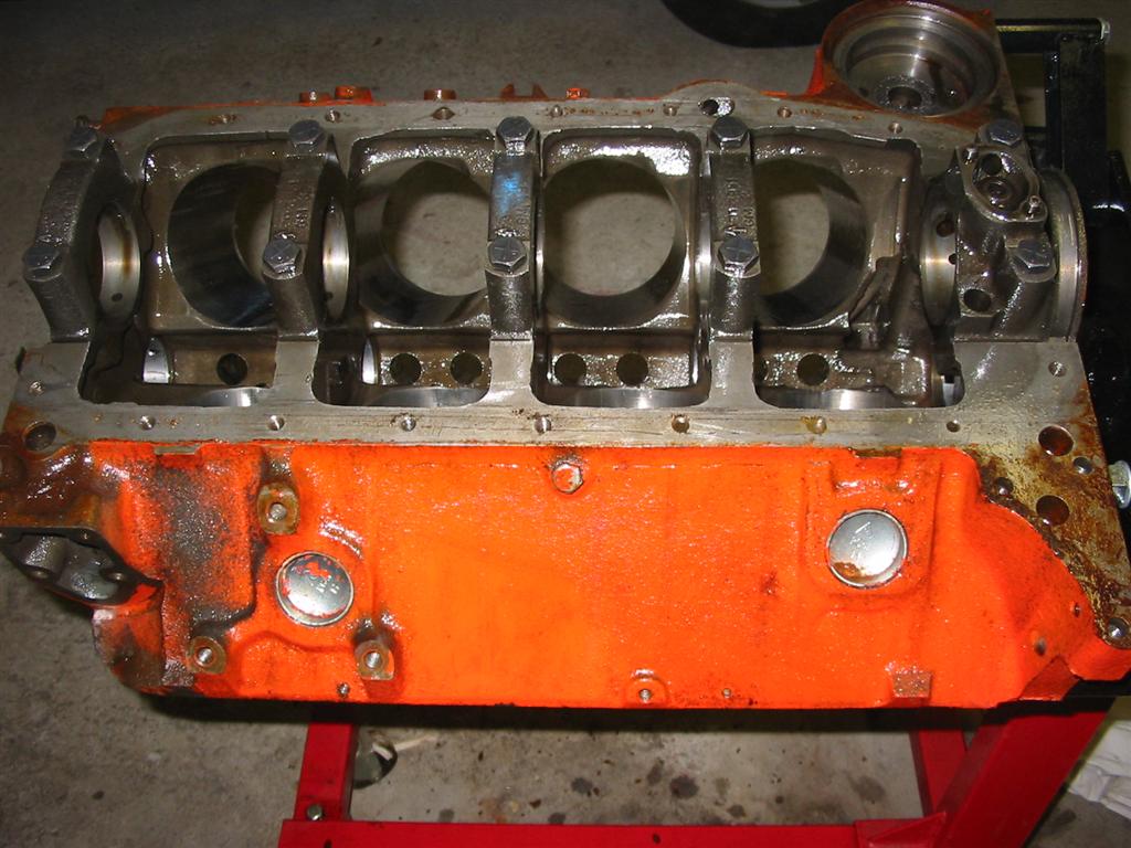
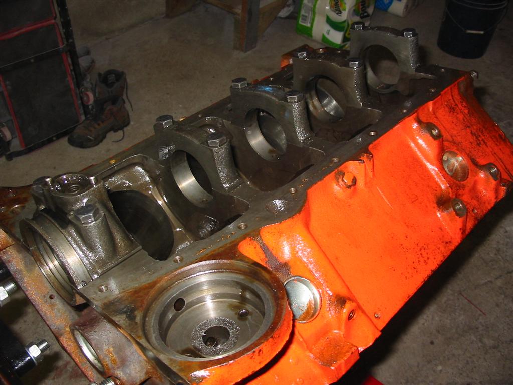
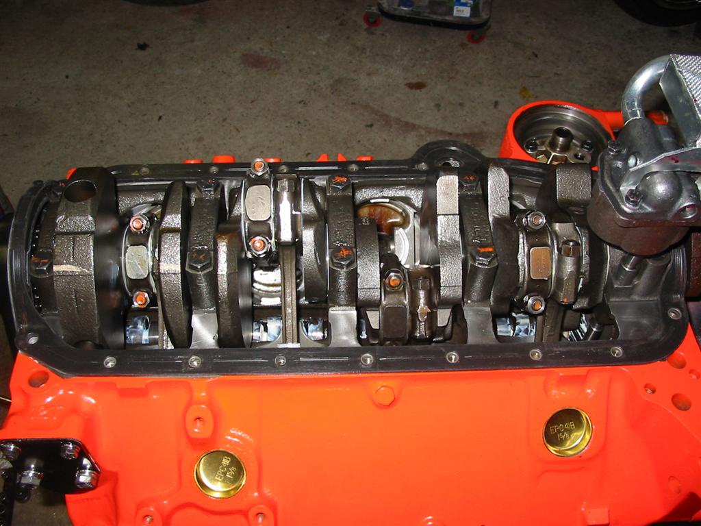
| Here is the crank and bottom end of the engine. Once again, there was no sludge and everything looked brand new. The oil pump pickup was clean and dirt free. The timing chain had no wear and will be reused. | |
|
|
|
|
|
|
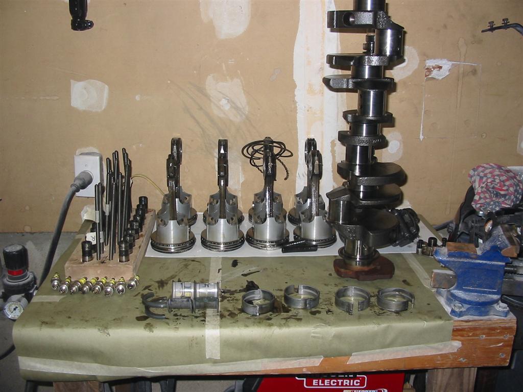
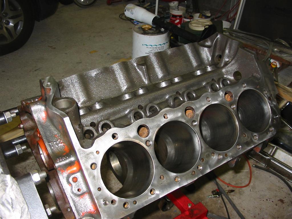
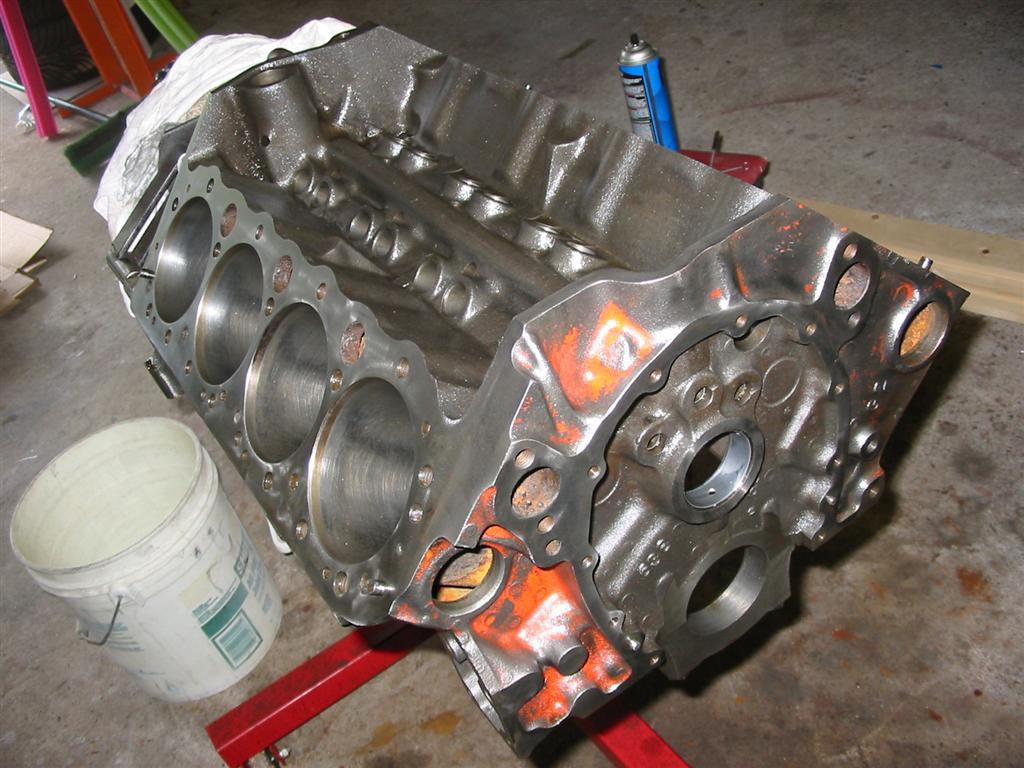
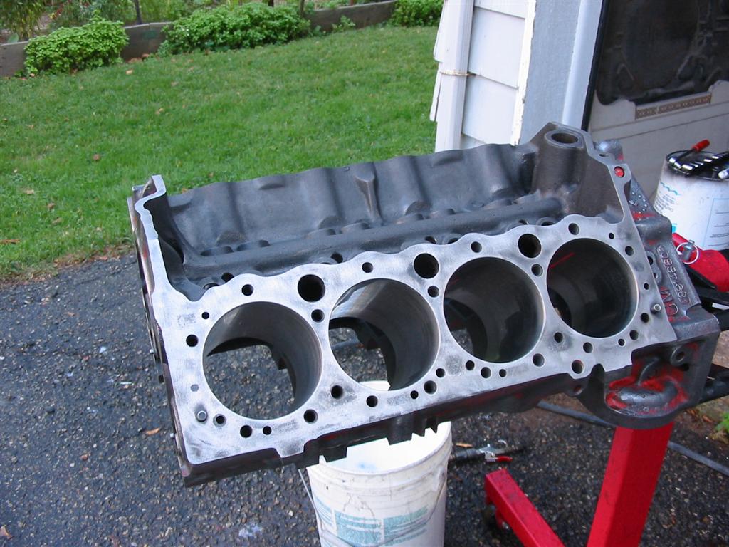
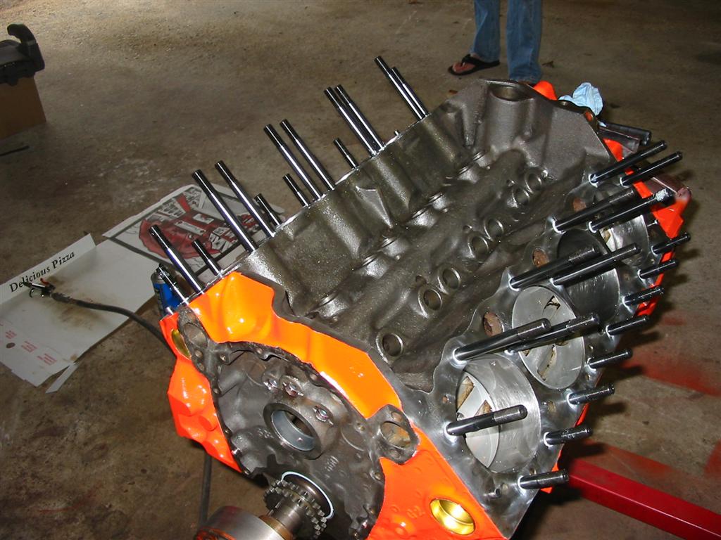
| Here is the unassembled block with all the internal parts removed. I stored the parts in a way to make sure they pistons and rods went back into their original bores. I also stored the lifters and pushrods in a way that allows me to put them back into the bores that they belong to. | |
|
|
|
|
|
|
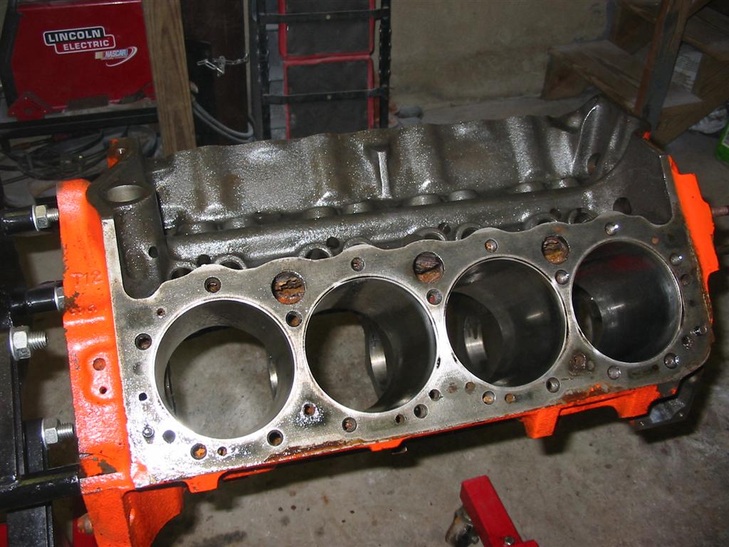
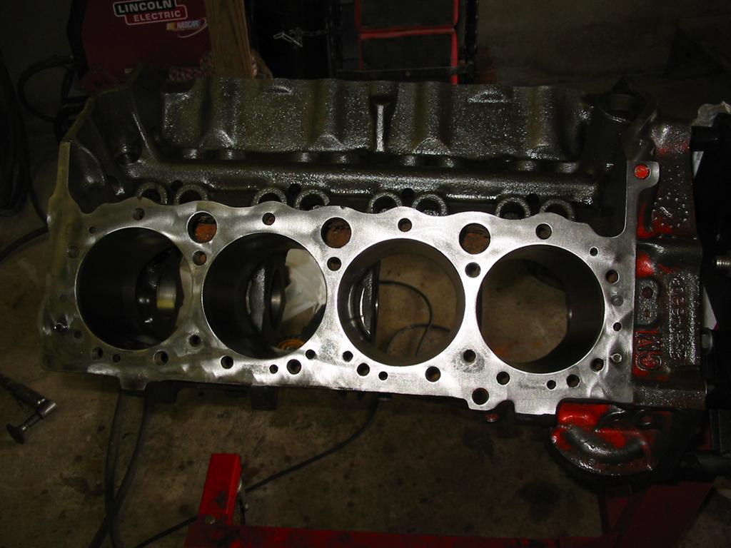
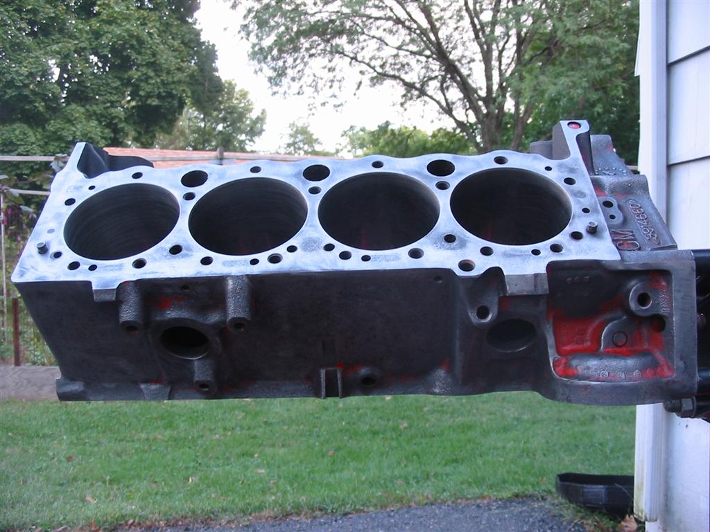
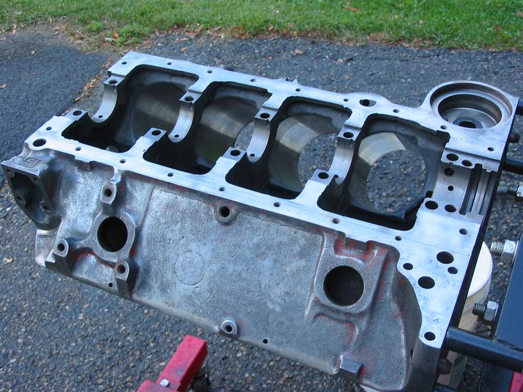
| I then stripped the paint from the block with a wire wheel and deburred some of the sharp edges and casting flash on the exterior of the block. | |
|
|
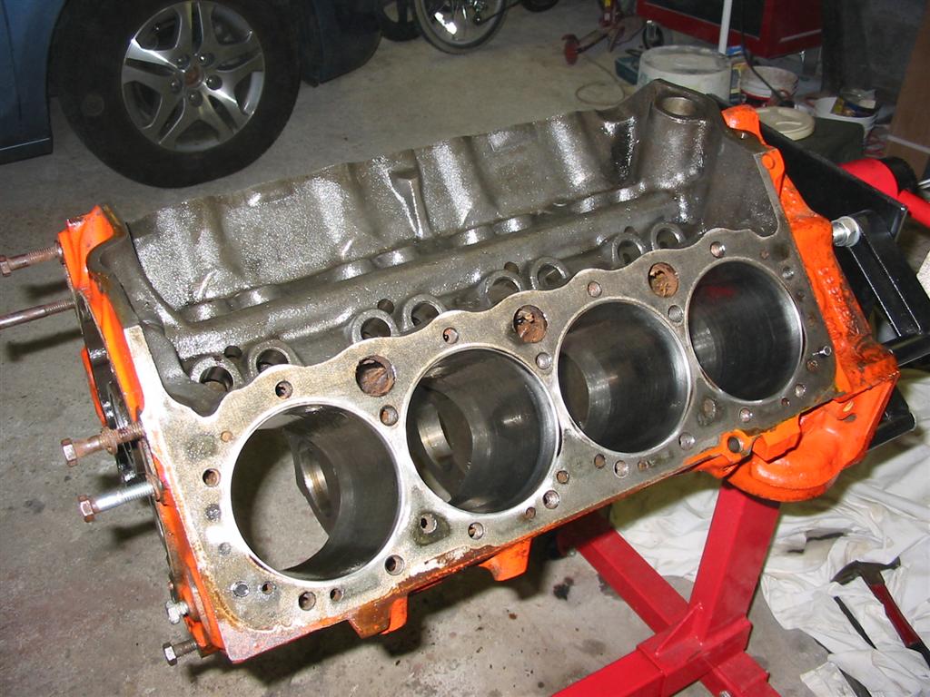
| I then honed the bores with a three stone hone and drill. | |
|
|
| The next step was to take the block outside and clean it with soapy water. I also used an engine brush kit to get into all the passages. | |
|
|
|
|
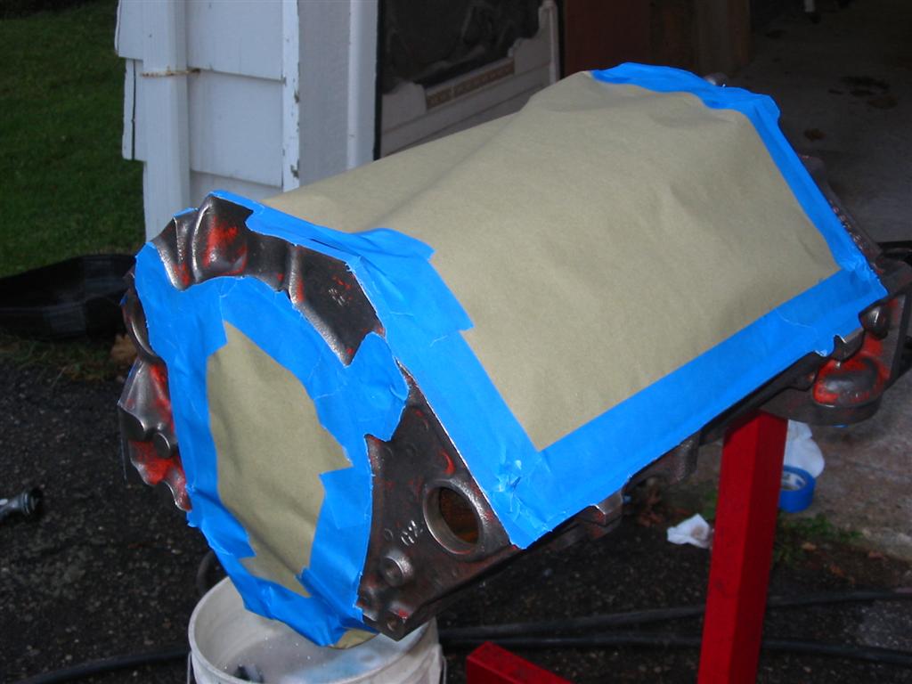
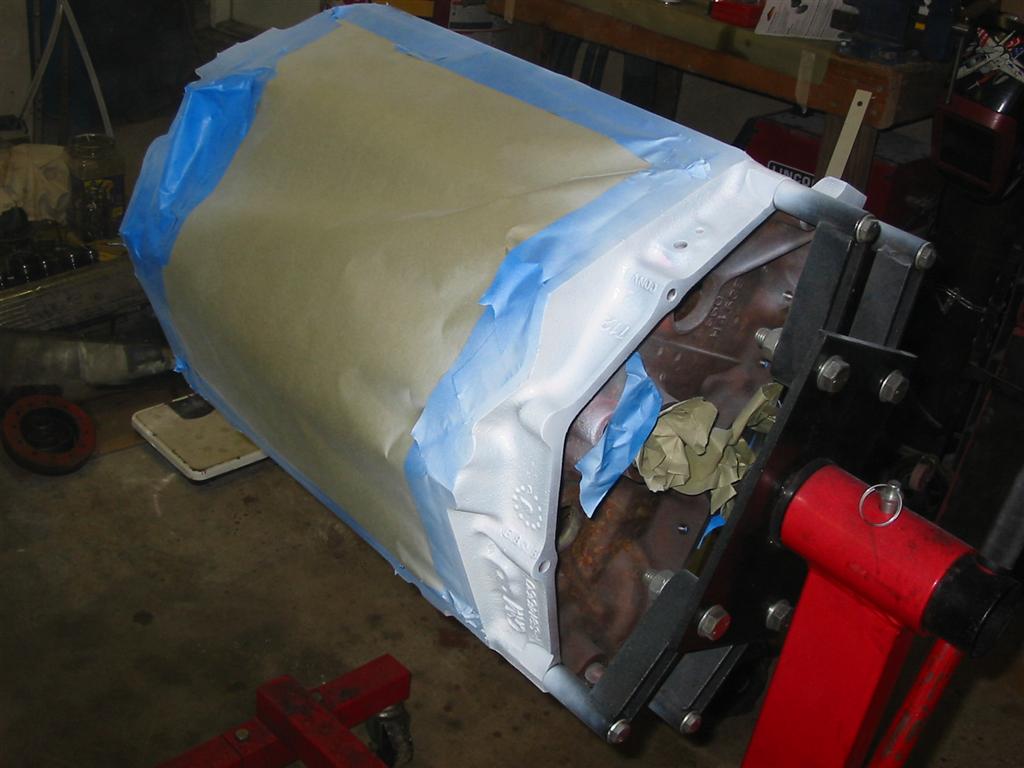
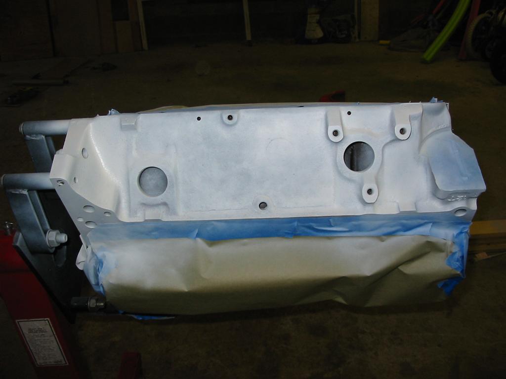
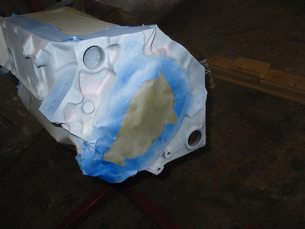
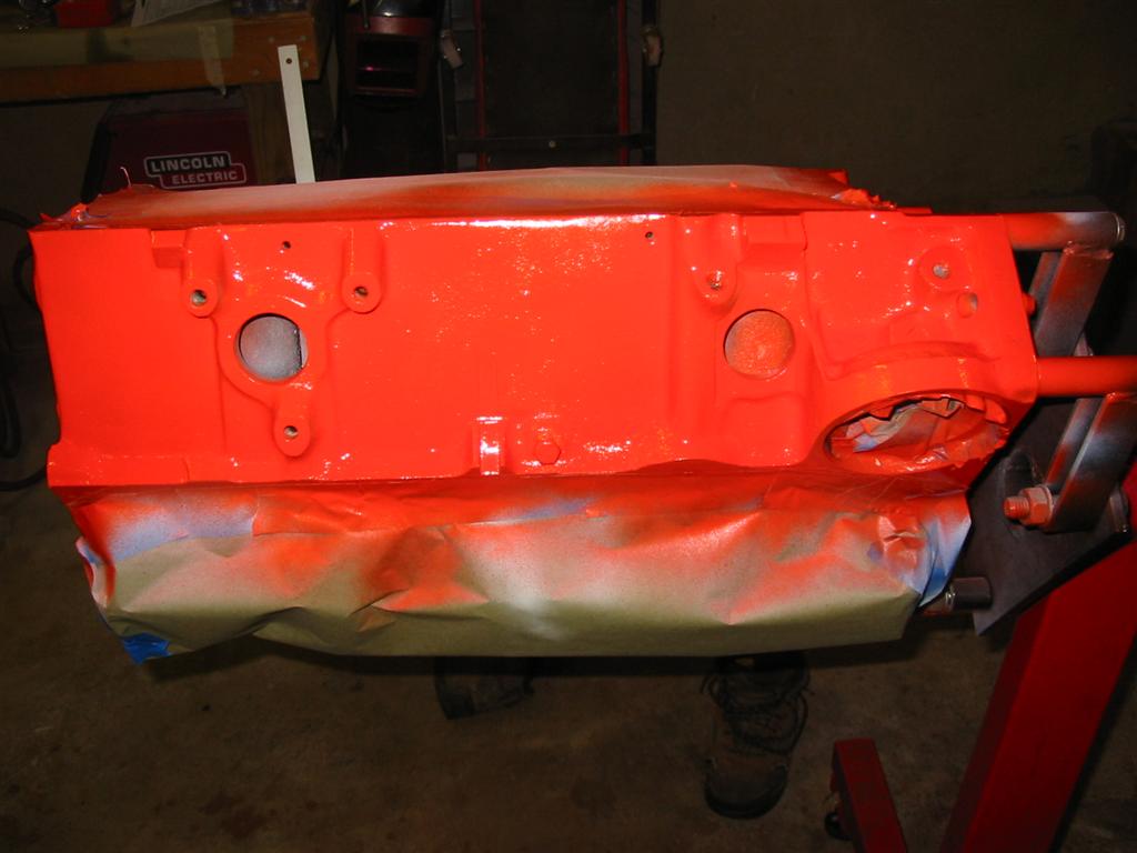
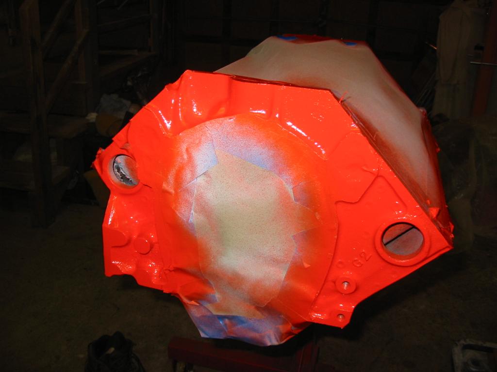
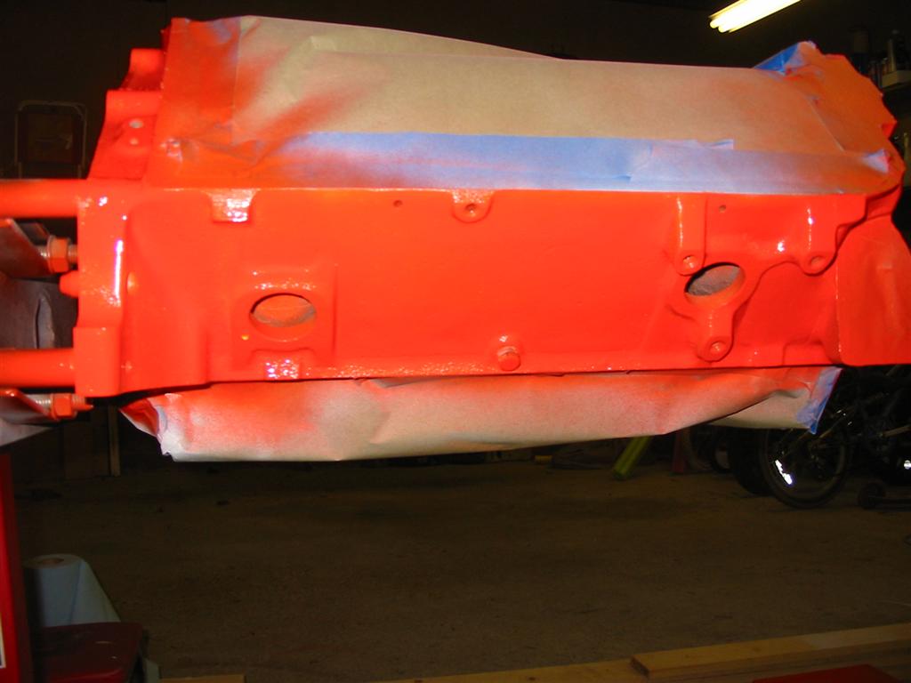
| I then masked the areas of the block that I did not want painted and then primed the engine with white high temp primer. | |
|
|
|
|
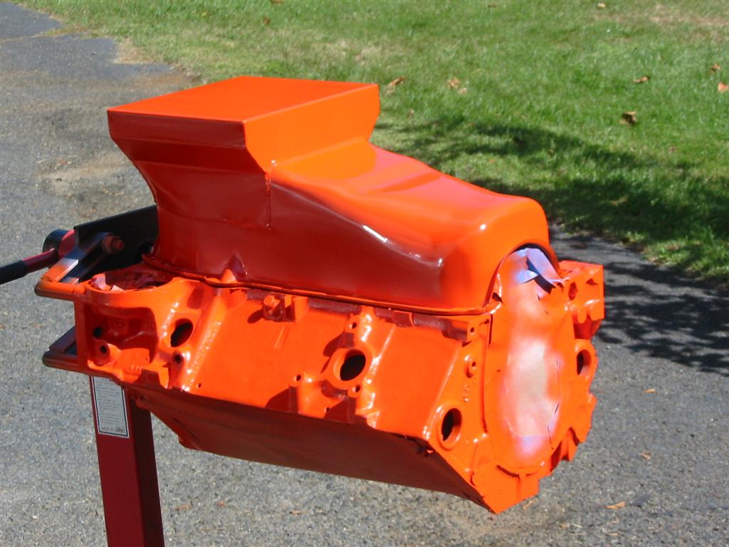
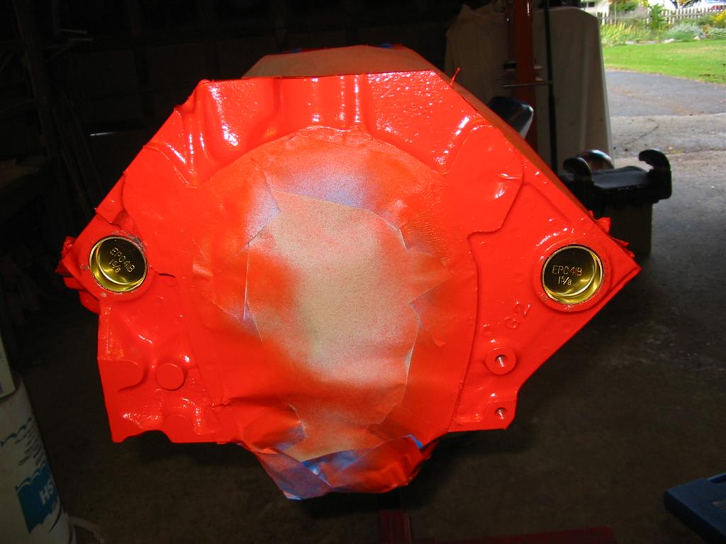
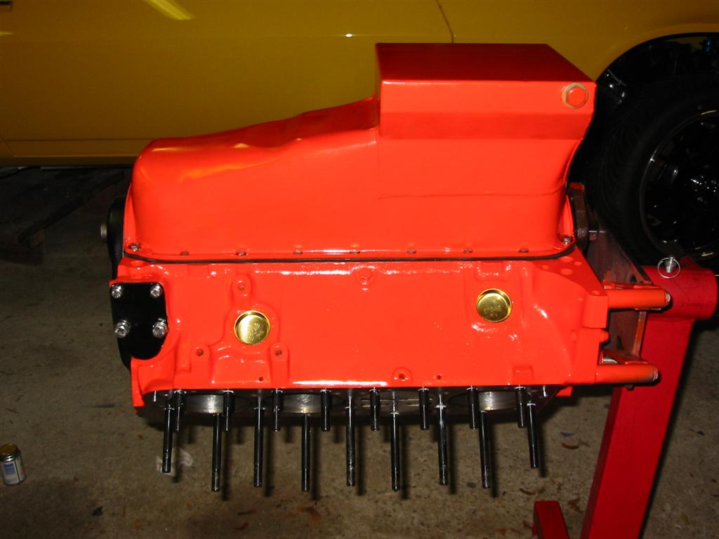
| The engine and oil pan then received a coat of Chevy Orange high temp engine paint. | |
|
|
|
|
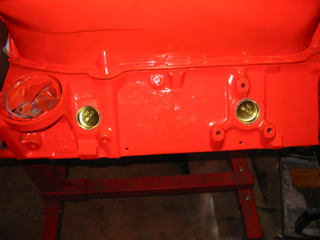
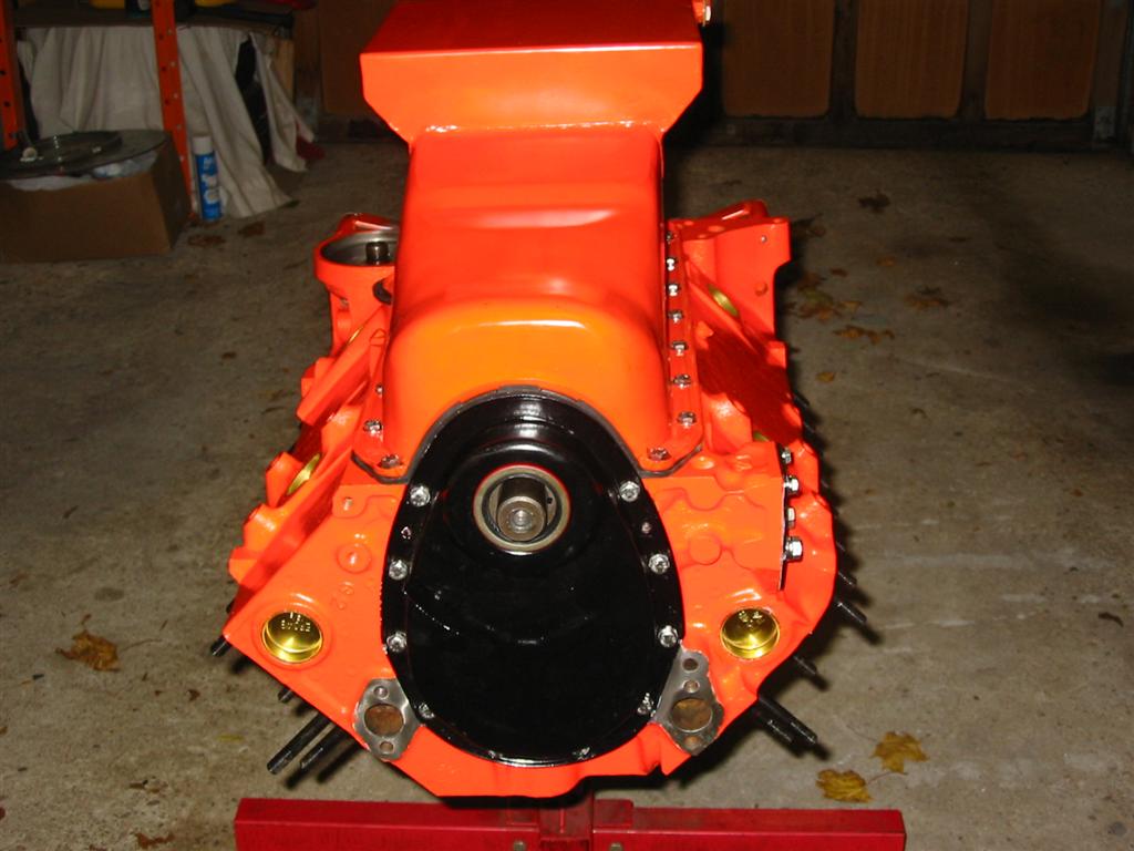
| The next step was to install freeze plugs. I decided to go with brass freeze plugs for there long term durability. | |
|
|
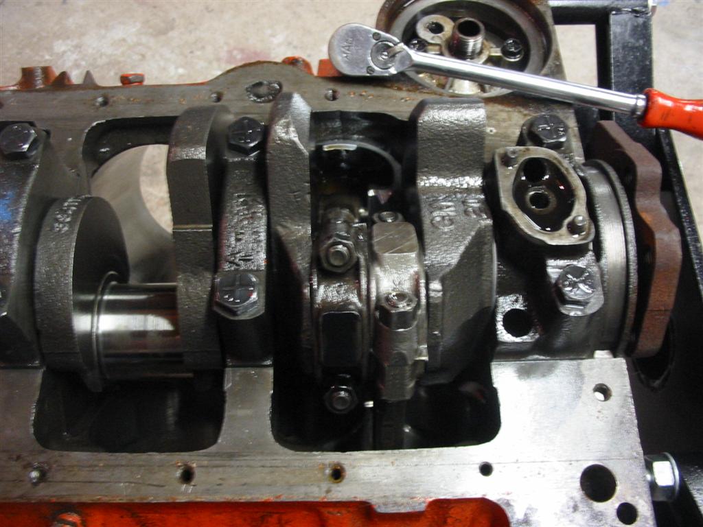
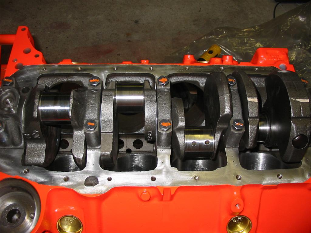
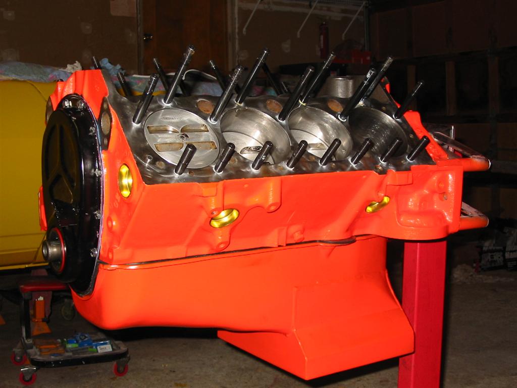
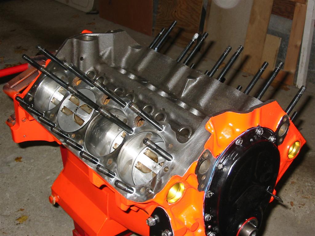
| Here are pictures of the crank installed followed by the installation of pistons and rods. Also seen is the installation of the ARP head studs. I went with head studs because I wanted to make sure that my aluminum heads seal properly. Studs do a better job of sealing than bolts. | |
|
|
|
|
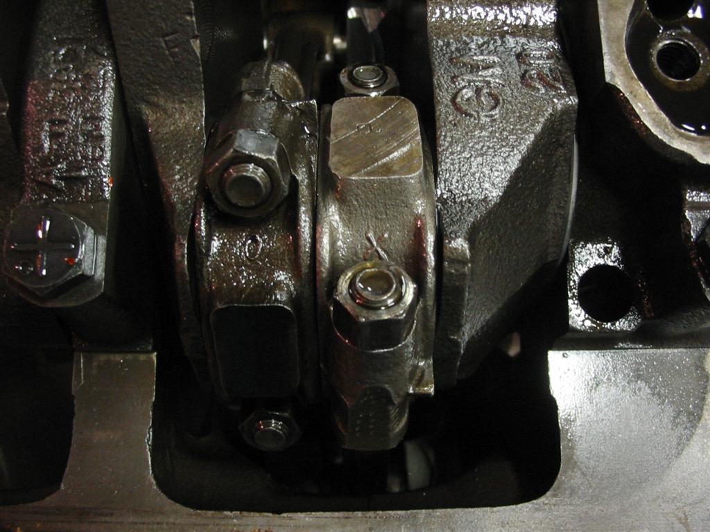
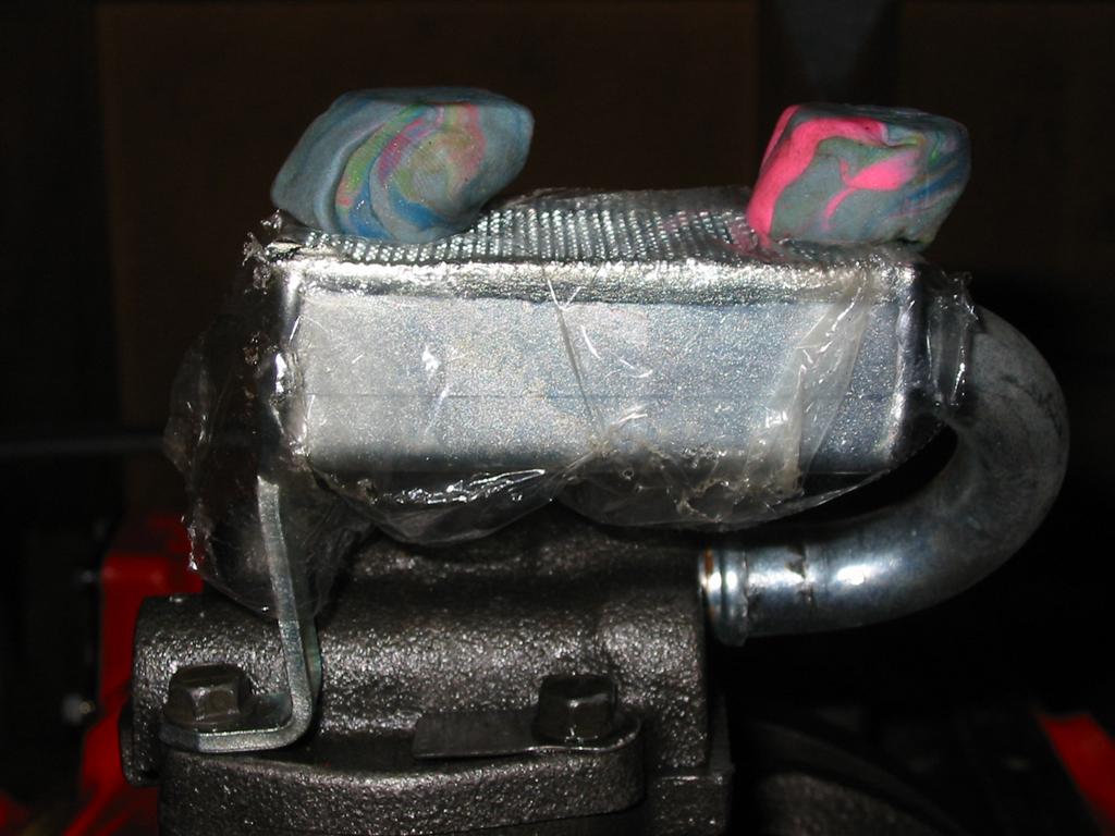
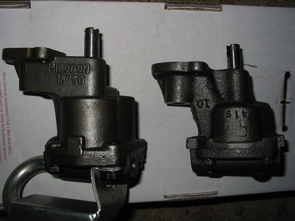
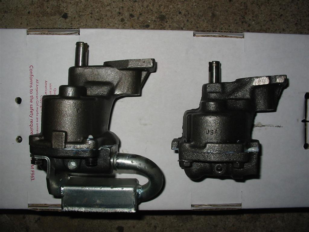
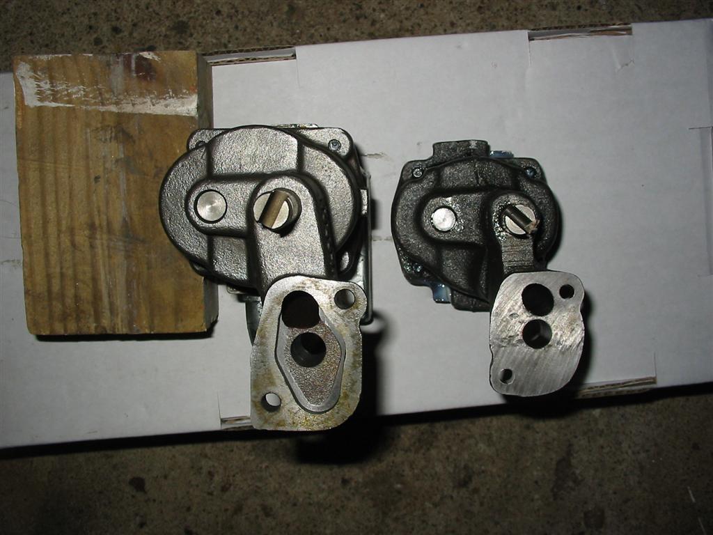
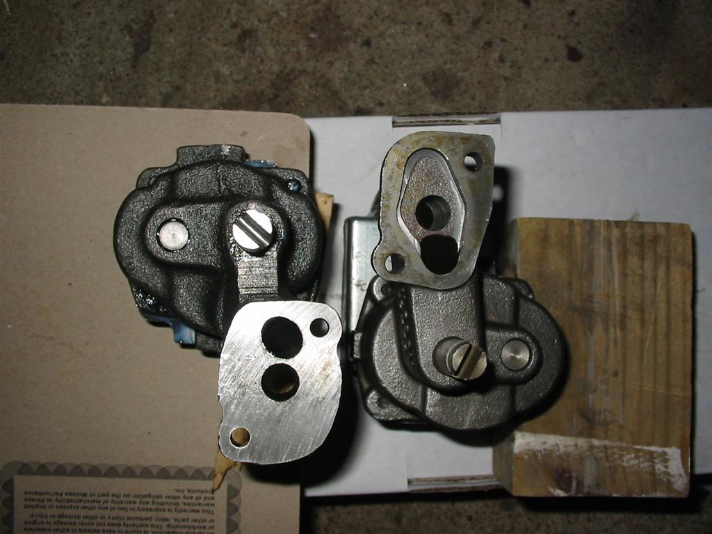
| The following photos are of my oil pump installation fiasco. I originally planned to use my original Melling pump. When I installed the pickup and measured the clearance, I noticed that I had over 5/8 of an inch of clearance between the pickup and the oil pan bottom. This was too much clearance and I attempted to bend the pickup up. This was a bad idea because I wound up breaking my oil pump cover. After doing some measurements, I found out why I had so much clearance. My pan was a 1/4 inch deeper than it was supposed to be and my Milodon one piece oil pan gasket was thicker that a normal gasket. To make things worse, I had just read on nastyz28.com that the new standard melling pumps were redesigned and prone to breaking in high performance applications. They now sold a new high performance pump for over 3 times the price of the standard pump. I then decided to go with the Milodon pump. Since the pump was taller, I just needed to tweak the pickup down a little bit to achieve 7/16 of an inch clearance. | |
|
|
|
|
|
|
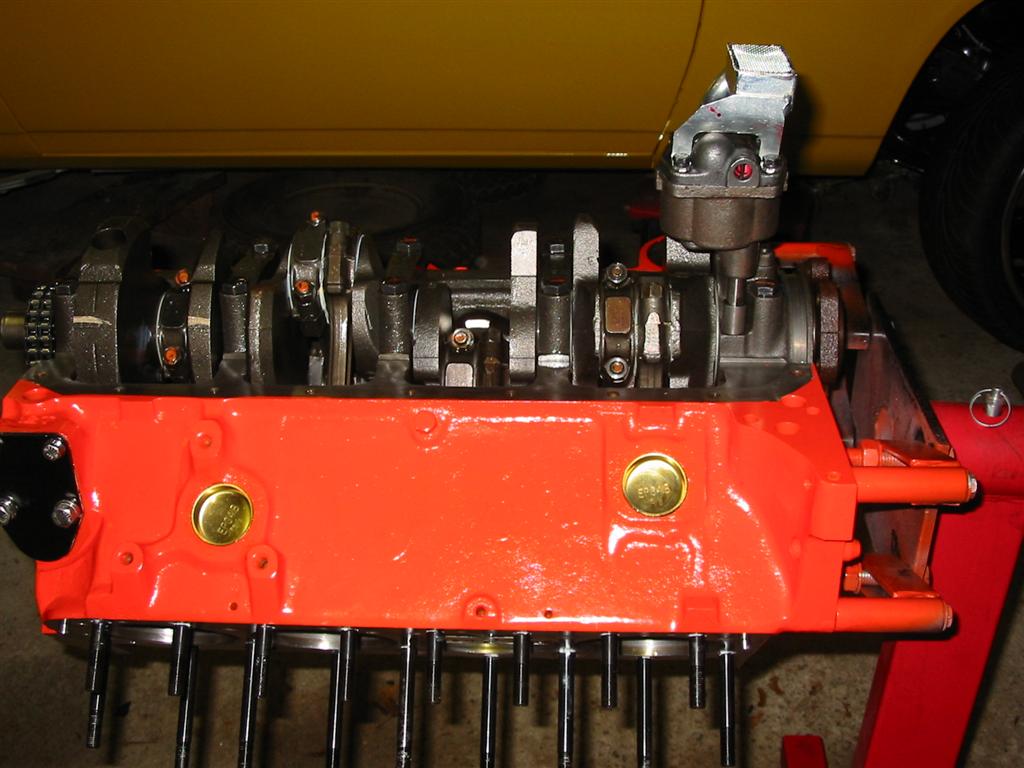
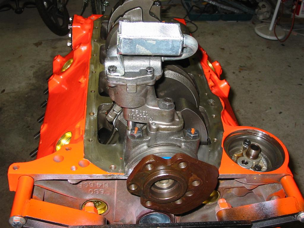
| Here is the pump and shaft installed. | |
|
|
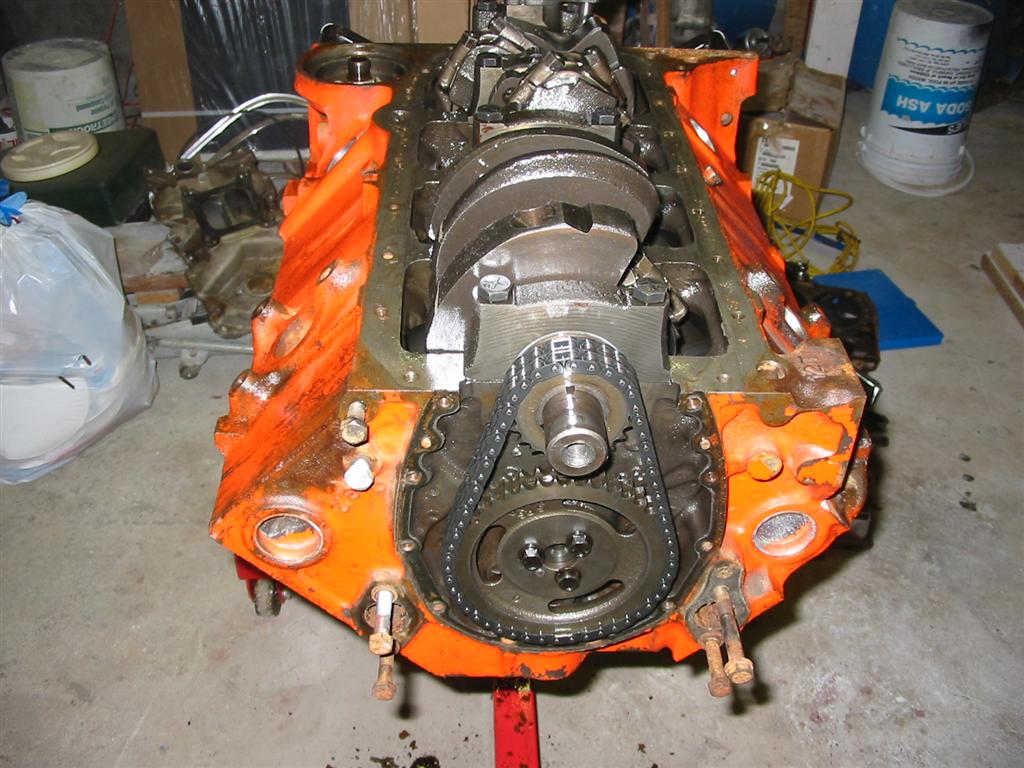
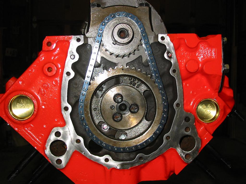
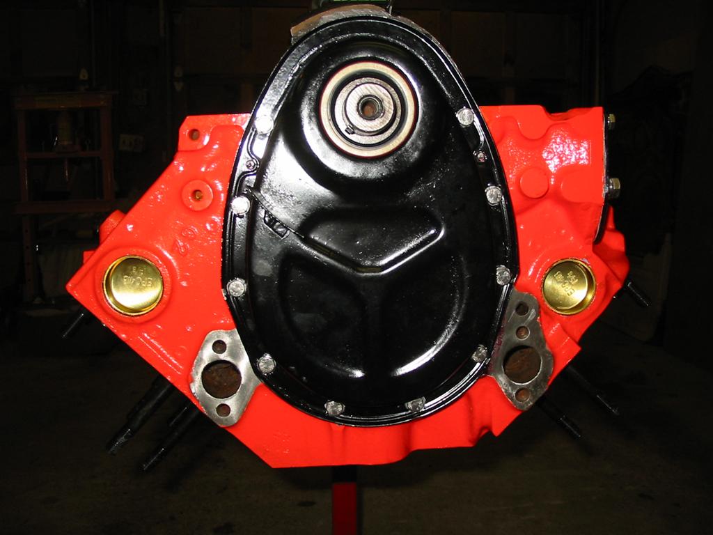
| Here is the camshaft and timing chain reinstalled. The camshaft is a Perfect Circle Super Performer Hydraulic camshaft (230 degrees duration at .050 lift with 0.453 total lift). I then installed the timing chain cover and secured the cover with stainless steel hardware. I made sure to use anti-seize on the bolts to prevent galvanic corrosion between the stainless steel and the iron block. | |
|
|
|
|
| Lastly, I installed the oil pan using a one piece Milodon oil pan gasket to seal the pan and stainless steel bolts to fasten the pan to the block. Once again, I used anti-seize on the stainless steel bolts. | |
|
|
|
|
|
|
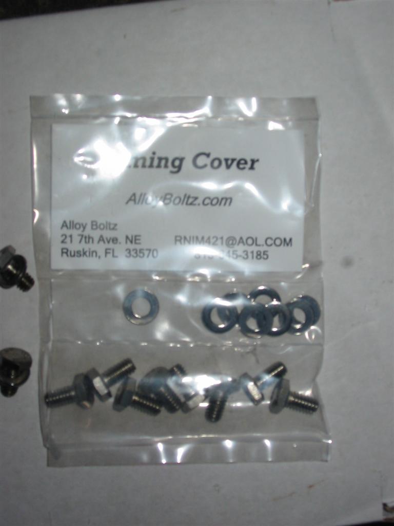
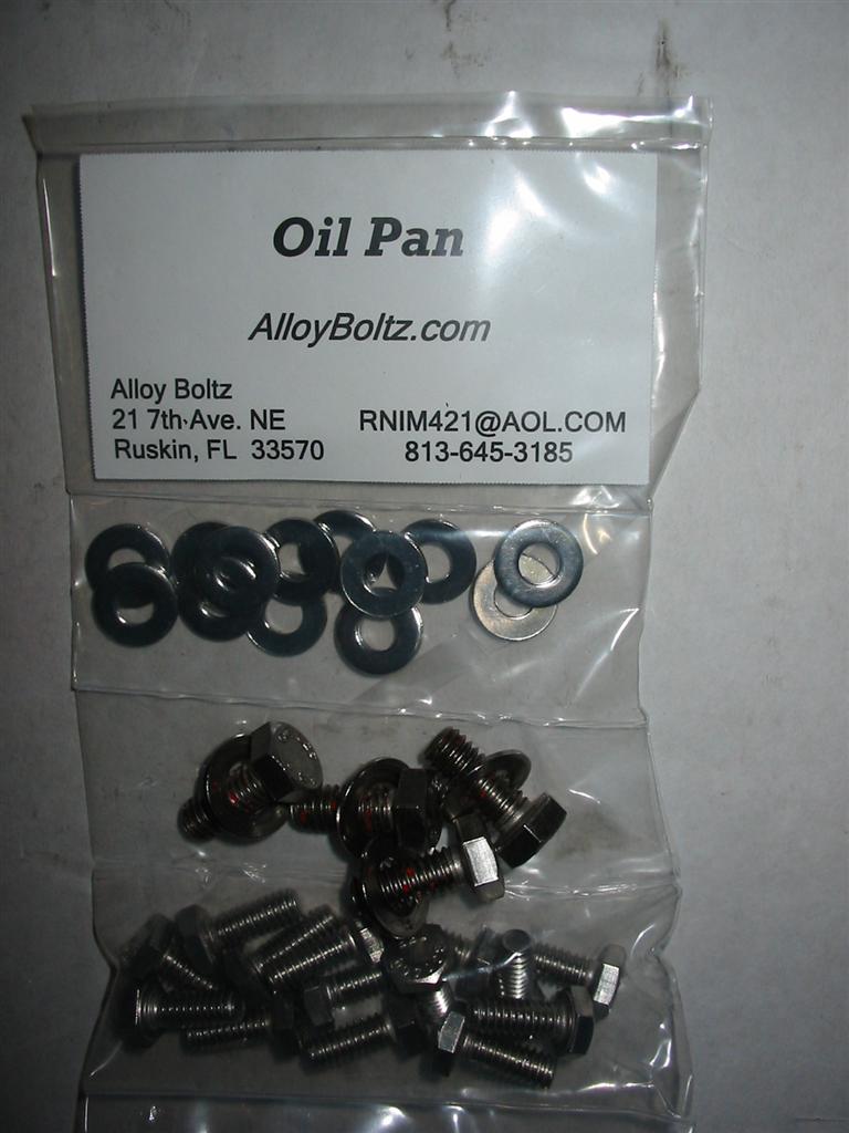
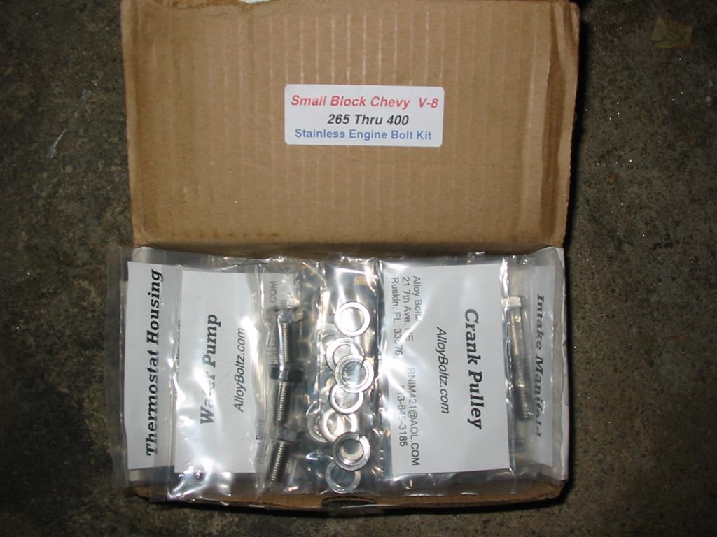
| Here is a picture of the stainless steel bolt kit that I purchased for the engine. | |
|
|